Process and Thread Distribution and Binding
What are we talking about in this session?

Distribution is the process of distributing processes and threads across the available resources of the job (nodes, sockets, NUMA nodes, cores, ...), and binding is the process of ensuring they stay there as naturally processes and threads are only bound to a node (OS image) but will migrate between cores. Binding can also ensure that processes cannot use resources they shouldn't use.
When running a distributed memory program, the process starter - mpirun or mpiexec
on many clusters, or srun on LUMI - will distribute the processes over the available
nodes. Within a node, it is possible to pin or attach processes or even individual threads
in processes to one or more cores (actually hardware threads) and other resources,
which is called process binding.
The system software (Linux, ROCm™ and Slurm) has several mechanisms for that. Slurm uses Linux cgroups or control groups to limit the resources that a job can use within a node and thus to isolate jobs from one another on a node so that one job cannot deplete the resources of another job, and sometimes even uses control groups at the task level to restrict some resources for a task (currently default behaviour when doing task-level GPU binding via Slurm). The second mechanism is processor affinity which works at the process and thread level and is used by Slurm at the task level and can be used by the OpenMP runtime to further limit thread migration. It works through affinity masks which indicate the hardware threads that a thread or process can use. There is also a third mechanism provided by the ROCm™) runtime to control which GPUs can be used.
Some of the tools in the lumi-CPEtools module can show the affinity mask for each thread
(or effectively the process for single-threaded processes) so you can use these tools to
study the affinity masks and check the distribution and binding of processes and threads.
The serial_check, omp_check, mpi_check and hybrid_check programs can be used to
study thread binding. In fact, hybrid_check can be used in all cases, but the other three
show more compact output for serial, shared memory OpenMP and single-threaded MPI processes
respectively. The gpu_check command can be used to study the steps in GPU binding.
From version 1.2 onwards, the module also contains the hpcat command, which stands for
HPC Affinity Tracker. This tool can only be compiled with Cray MPICH, but it shows core
affinity, GPUs used and, when running on more than one node, the network adapter used by
each MPI rank. It shows the NUMA node for all these resources so that it is easy to check
if the binding is OK.
Credits for these programs (click to expand)
The hybrid_check program and its derivatives serial_check, omp_check and mpi_check
are similar to the xthi program
used in many of the advanced courses organised by the LUST in collaboration with
HPE Cray and AMD. Its main source of inspiration is a very similar program,
acheck, written by Harvey Richardson of HPE Cray and used in an earlier course,
but it is a complete rewrite of that application.
One of the advantages of hybrid_check and its derivatives is that the output is
sorted internally already and hence is more readable. The tool also has various extensions,
e.g., putting some load on the CPU cores so that you can in some cases demonstrate thread
migration as the Linux scheduler tries to distribute the load in a good way.
The gpu_check program builds upon the
hello_jobstep program from ORNL
with several extensions implemented by the LUST.
(ORNL is the national lab that operates Frontier, an exascale supercomputer based on the same node type as LUMI-G.)
The HPC Affinity Tracker tool is developed by HPE and made publicly available in GitHub.

In this section we will consider process and thread distribution and binding at several levels:
-
When creating an allocation, Slurm will already reserve resources at the node level, but this has been discussed already in the Slurm session of the course.
It will also already employ control groups to restrict the access to those resources on a per-node per-job basis.
-
When creating a job step, Slurm will distribute the tasks over the available resources, bind each task to CPUs allocated to that task, and depending on how the job step was started, bind each task to the GPUs allocated to the task or to the subset of the GPUs available to the job step on the node the task is running on.
-
With Cray MPICH, you can change the binding between MPI ranks and Slurm tasks. Normally MPI rank i would be assigned to task i in the job step, but sometimes there are reasons to change this. The mapping options offered by Cray MPICH are more powerful than what can be obtained with the options to change the task distribution in Slurm.
-
The OpenMP runtime also uses library calls and environment variables to redistribute and pin threads within the subset of hardware threads available to the process. Note that different compilers use different OpenMP runtimes so the default behaviour will not be the same for all compilers, and on LUMI is different for the Cray compiler compared to the GNU and AMD compilers.
-
The ROCm™ runtime also can limit the use of GPUs by a process to a subset of the ones that Slurm allocated to the task through the use of the
ROCR_VISIBLE_DEVICESenvironment variable. -
Binding can also be done by calling APIs inside the program: HIP, libnuma, etc., all provide binding APIs to the application, but that is very application-specific and cannot be covered in this presentation.
An example of such an application is
torchrun, where you need to set bindings in your Python script itself as discussed in the LUMI AI Guide.
Binding almost only makes sense on job-exclusive nodes as only then you have full control over all available resources. On "allocatable by resources" partitions you usually do not know which resources are available. The advanced Slurm binding options that we will discuss do not work in those cases, and the options offered by the MPICH, OpenMP and ROCm™ runtimes may work very unpredictable, though OpenMP thread binding may still help a bit with performance in some cases.
Warning
Note also that some srun options that we have seen (sometimes already given at the sbatch or salloc level
but picked up by srun) already do a simple binding, so those options cannot be combined with the options
that we will discuss in this session. This is the case for --cpus-per-task, --gpus-per-task and --ntasks-per-gpu.
In fact, the latter two options will also change the numbering of the GPUs visible to the ROCm runtime, so
using ROCR_VISIBLE_DEVICES may also lead to surprises!
Why do I need this?

As we have seen in the "LUMI Architecture" session of this course and as you may know from other courses, modern supercomputer nodes have increasingly a very hierarchical architecture. This hierarchical architecture is extremely pronounced on the AMD EPYC architecture used in LUMI but is also increasingly showing up with Intel processors and the ARM server processors, and is also relevant but often ignored in GPU clusters.
A proper binding of resources to the application is becoming more and more essential for good performance and scalability on supercomputers.
-
Memory locality is very important, and even if an application would be written to take the NUMA character properly into account at the thread level, a bad mapping of these threads to the cores may result into threads having to access memory that is far away (with the worst case on a different socket) extensively.
Memory locality at the process level is easy as usually processes share little or no memory. So if you would have an MPI application where each rank needs 14 GB of memory and so only 16 ranks can run on a regular node, then it is essential to ensure that these ranks are spread out nicely over the whole node, with one rank per CCD. The default of Slurm when allocating 16 single-thread tasks on a node would be to put them all on the first two CCDs, so the first NUMA-domain, which would give very poor performance as a lot of memory accesses would have to go across sockets.
-
If threads in a process don't have sufficient memory locality it may be very important to run all threads in as few L3 cache domains as possible, ideally just one, as otherwise you risk having a lot of conflicts between the different L3 caches that require resolution and can slow down the process a lot.
This already shows that there is no single works-for-all solution, because if those threads would use all memory on a node and each have good memory locality then it would be better to spread them out as much possible. You really need to understand your application to do proper resource mapping, and the fact that it can be so application-dependent is also why Slurm and the various runtimes cannot take care of it automatically.
-
In some cases it is important on the GPU nodes to ensure that tasks are nicely spread out over CCDs with each task using the GPU (GCD) that is closest to the CCD the task is running on. This is certainly the case if the application would rely on cache-coherent access to GPU memory from the CPU, but also helps if there is a lot of copying going on between CPU and GPU memory.
-
With careful mapping of MPI ranks on nodes you can often reduce the amount of inter-node data transfer in favour of the faster intra-node transfers. This requires some understanding of the communication pattern of your MPI application, but there are profiling tools for that that are discussed in the advanced courses.
-
For GPU-aware MPI: Check if the intra-node communication pattern can map onto the links between the GCDs.
How can I check the bindings?

There are several ways to check the bindings.
In some cases, only application-specific ways are available as the binding is partly or wholly done in the application. This is, e.g., the case in some AI applications where the binding is arranged in the Python script itself.
For applications that simply use OpenMP and/or MPI, there are usually environment variables that depend on the OpenMP and MPI implementation to print additional debug information that includes some binding information. That information is sometimes hard to decode.
For LUMI, the support team developed the
LUMI-CPEtools module.
There is a separate version for each of the toolchains in the LUMI software stack as
the behaviour of the OpenMP runtime is sometimes compiler-specific. The module contains
several small programs that run quickly and that you start in the same way as you would
start your application, so that they would display the bindings the way they would be done
in your application.
Tools include:
-
serial_check,omp_check,mpi_checkandhybrid_checkare 4 similar tools to show information about the CPU bindings.serial_checkis for sequential programs and hence somewhat trivial.omp_checkis for shared memory applications using OpenMP.mpi_checkis for MPI applications that have no additional level of shared memory parallelism in each MPI rank.hybrid_mpiis for applications that combine MPI with OpenMP shared memory parallelisation within each MPI rank. The last two commands can also be used to study bindings in heterogeneous jobs. -
gpu_checkis a similar command that will also display the GPU bindings and gives output in a way that makes it easier to check if the GPU bindings are optimal. It is a hybrid program but can be used for all types of jobs (with or without MPI or CPU OpenMP parallelism). -
hpcatis a tool developed by HPE. It shows task and thread bindings, GPU bindings and network interface bindings. While the other tools can in principle be recompiled for different MPI implementations,hpcatcurrently only works with Cray MPICH as it uses mechanism specific to that implementation to report on the network interface bindings.Unfortunately, the main developer has left the company so its future is a bit unclear which is why we still mostly use the other tools in this chapter.
In any case, we strongly recommend that you check the bindings when you have made changes in your job script that may affect bindings, and these tools can be very useful. We will use them throughout examples in this chapter of the tutorial.
Using the gpu_check tool
To demonstrate the gpu_check tool and how to interpret the output, run the
example jobscript:
#!/bin/bash
#SBATCH --account=project_46YXXXXXX
#SBATCH --job-name=gpucheck-demo
#SBATCH --output %x-%j.txt
#SBATCH --partition=standard-g
#SBATCH --gpus-per-node=8
#SBATCH --nodes=1
#SBATCH --time=5:00

module load LUMI/25.03 lumi-CPEtools/1.2-cpeGNU-25.03-hpcat-0.9

gpu_check --help

echo -e "\n8 tasks with 1 GPU each, without --gres-flags=allow-task-sharing:\n"
srun --ntasks=$((SLURM_NNODES*8)) \
     --cpu-bind="map_cpu:49,57,17,25,1,9,33,41" \
     --gpu-bind="map:0,1,2,3,4,5,6,7" \
     gpu_check -l

echo -e "\n8 tasks with 1 GPU each, with --gres-flags=allow-task-sharing:\n"
srun --ntasks=$((SLURM_NNODES*8)) \
     --cpu-bind="map_cpu:49,57,17,25,1,9,33,41" \
     --gpu-bind="map:0,1,2,3,4,5,6,7" \
     --gres-flags=allow-task-sharing \
     gpu_check -l

echo -e "\n4 tasks with 2 GPUs each, without --gres-flags=allow-task-sharing:\n"
srun --ntasks=$((SLURM_NNODES*4)) \
     --cpu-bind="map_cpu:49,17,1,33" \
     --gpu-bind="mask:0x03,0x0c,0x30,0xc0" \
     gpu_check -l

echo -e "\n4 tasks with 2 GPUs each, with --gres-flags=allow-task-sharing:\n"
srun --ntasks=$((SLURM_NNODES*4)) \
     --cpu-bind="map_cpu:49,17,1,33" \
     --gpu-bind="mask:0x03,0x0c,0x30,0xc0" \
     --gres-flags=allow-task-sharing \
     gpu_check -l
First, some help for the gpu_check command is printed:
gpu_check

Flags accepted:

  -h, --help Show help information and exit
  -l, --fl   Shows a bit more information: CCD with the thread number
             and GCD and optimal CCD with the PCIe bus ID
  -u         Unsorted printing, may work around some bugs

Meaning of the output:

  MPI:       Rank of the MPI process
  OMP:       OpenMP thread number
  HWT:       Hardware thread
  RT_GPU_ID: HIP runtime GPU ID, a local ID, a series starting from 0 for
             each process.
  GPU_ID:    Value of ROCR_VISIBLE_DEVICES. This could refer to the global
             GPU IDs, but a scheduler can actually remap the GPU numbering
             to (in case of Slurm) IDs starting from 0 for each task.
  Bus_ID:    PCIe bus ID and the only truly reliable way to identify a
             physical GPU.

Hardware mapping:

  CPU die 0 providing HWT 000-007 and 064-071 to GPU die 4 with Bus_ID d1
  CPU die 1 providing HWT 008-015 and 072-079 to GPU die 5 with Bus_ID d6
  CPU die 2 providing HWT 016-023 and 080-087 to GPU die 2 with Bus_ID c9
  CPU die 3 providing HWT 024-031 and 088-095 to GPU die 3 with Bus_ID ce
  CPU die 4 providing HWT 032-039 and 096-103 to GPU die 6 with Bus_ID d9
  CPU die 5 providing HWT 040-047 and 104-111 to GPU die 7 with Bus_ID de
  CPU die 6 providing HWT 048-055 and 112-119 to GPU die 0 with Bus_ID c1
  CPU die 7 providing HWT 056-063 and 120-127 to GPU die 1 with Bus_ID c6

  GPU die 0 with Bus_ID c1 to CPU die 6 providing HWT 048-055 and 112-119
  GPU die 1 with Bus_ID c6 to CPU die 7 providing HWT 056-063 and 120-127
  GPU die 2 with Bus_ID c9 to CPU die 2 providing HWT 016-023 and 080-087
  GPU die 3 with Bus_ID ce to CPU die 3 providing HWT 024-031 and 088-095
  GPU die 4 with Bus_ID d1 to CPU die 0 providing HWT 000-007 and 064-071
  GPU die 5 with Bus_ID d6 to CPU die 1 providing HWT 008-015 and 072-079
  GPU die 6 with Bus_ID d9 to CPU die 4 providing HWT 032-039 and 096-103
  GPU die 7 with Bus_ID de to CPU die 5 providing HWT 040-047 and 104-111

Restrictions:

  - This tool currently only works for Cray EX bardpeak nodes (Trento + 4 * MI250X).
The important information in the output are the RT_GPU_ID, GPU_ID and Bus_ID
fields. The first one shows the numbers of the GPUs as seen in the HIP runtime.
The second shows the value for ROCR_VISIBLE_DEVICES and the third field
shows the PCIe ID of the GPU being used from which the physical GCD number can also
be derived. If the RT_GPU_ID and GPU_ID column are the same for all tasks
on a node while the Bus_ID columns are different, then it is rather likely that
you did the binding in a way that GPUs cannot communicate through the IPC mechanism and
that you will have issues with RCCL and MPI.
Consider, e.g., the output for the case where we use Slurm for CPU and GPU binding
with one core and one GCD per task, either without or with --gres-flags=allow-task-sharing:
8 tasks with 1 GPU each, without --gres-flags=allow-task-sharing:

MPI 000 - OMP 000 - HWT 049 (CCD6) - Node nid005496 - RT_GPU_ID 0 - GPU_ID 0 - Bus_ID d1(GCD4/CCD0)
MPI 001 - OMP 000 - HWT 057 (CCD7) - Node nid005496 - RT_GPU_ID 0 - GPU_ID 0 - Bus_ID d6(GCD5/CCD1)
MPI 002 - OMP 000 - HWT 017 (CCD2) - Node nid005496 - RT_GPU_ID 0 - GPU_ID 0 - Bus_ID c9(GCD2/CCD2)
MPI 003 - OMP 000 - HWT 025 (CCD3) - Node nid005496 - RT_GPU_ID 0 - GPU_ID 0 - Bus_ID ce(GCD3/CCD3)
MPI 004 - OMP 000 - HWT 001 (CCD0) - Node nid005496 - RT_GPU_ID 0 - GPU_ID 0 - Bus_ID d9(GCD6/CCD4)
MPI 005 - OMP 000 - HWT 009 (CCD1) - Node nid005496 - RT_GPU_ID 0 - GPU_ID 0 - Bus_ID de(GCD7/CCD5)
MPI 006 - OMP 000 - HWT 033 (CCD4) - Node nid005496 - RT_GPU_ID 0 - GPU_ID 0 - Bus_ID c1(GCD0/CCD6)
MPI 007 - OMP 000 - HWT 041 (CCD5) - Node nid005496 - RT_GPU_ID 0 - GPU_ID 0 - Bus_ID c6(GCD1/CCD7)

8 tasks with 1 GPU each, with --gres-flags=allow-task-sharing:

MPI 000 - OMP 000 - HWT 049 (CCD6) - Node nid005496 - RT_GPU_ID 0 - GPU_ID 0 - Bus_ID c1(GCD0/CCD6)
MPI 001 - OMP 000 - HWT 057 (CCD7) - Node nid005496 - RT_GPU_ID 0 - GPU_ID 1 - Bus_ID c6(GCD1/CCD7)
MPI 002 - OMP 000 - HWT 017 (CCD2) - Node nid005496 - RT_GPU_ID 0 - GPU_ID 2 - Bus_ID c9(GCD2/CCD2)
MPI 003 - OMP 000 - HWT 025 (CCD3) - Node nid005496 - RT_GPU_ID 0 - GPU_ID 3 - Bus_ID ce(GCD3/CCD3)
MPI 004 - OMP 000 - HWT 001 (CCD0) - Node nid005496 - RT_GPU_ID 0 - GPU_ID 4 - Bus_ID d1(GCD4/CCD0)
MPI 005 - OMP 000 - HWT 009 (CCD1) - Node nid005496 - RT_GPU_ID 0 - GPU_ID 5 - Bus_ID d6(GCD5/CCD1)
MPI 006 - OMP 000 - HWT 033 (CCD4) - Node nid005496 - RT_GPU_ID 0 - GPU_ID 6 - Bus_ID d9(GCD6/CCD4)
MPI 007 - OMP 000 - HWT 041 (CCD5) - Node nid005496 - RT_GPU_ID 0 - GPU_ID 7 - Bus_ID de(GCD7/CCD5)
Comparing the CCD numbers shown for the HWT and at the end at the Bus_ID, we see that the
mapping is correct as they are the same (at the end the relevant part of the PCIe bus ID is shown
together with the physical GCD number and the matching CCD number).
In the first case, we see that the RT_GPU_ID and GPU_ID values are the same for all MPI ranks
while it is clear from the Bus_ID column that the GPUs are different.
This is because each task has its own cgroup for GPUs, so that the numbering that has to be used
for ROCR_VISIBLE_DEVICES is always 0 as there is only one GPU in that cgroup.
In the second case, RT_GPU_ID is always 0 as the HIP runtime has only one GPU available,
but the values for GPU_ID are different and range from 0 to 7. This is because now all GPUs are
visible to all tasks on the node, and ROCR_VISIBLE_DEVICES is used by Slurm to set the GPU
available to the ROCm™ runtime for each task.
Next we try the same experiment, but now with 4 MPI ranks that each get one core and 2 GCDs. Now we get:
4 tasks with 2 GPUs each, without --gres-flags=allow-task-sharing:

MPI 000 - OMP 000 - HWT 049 (CCD6) - Node nid006641 - RT_GPU_ID 0,1 - GPU_ID 0,1 - Bus_ID d1(GCD4/CCD0),d6(GCD5/CCD1)
MPI 001 - OMP 000 - HWT 017 (CCD2) - Node nid006641 - RT_GPU_ID 0,1 - GPU_ID 0,1 - Bus_ID c9(GCD2/CCD2),ce(GCD3/CCD3)
MPI 002 - OMP 000 - HWT 001 (CCD0) - Node nid006641 - RT_GPU_ID 0,1 - GPU_ID 0,1 - Bus_ID d9(GCD6/CCD4),de(GCD7/CCD5)
MPI 003 - OMP 000 - HWT 033 (CCD4) - Node nid006641 - RT_GPU_ID 0,1 - GPU_ID 0,1 - Bus_ID c1(GCD0/CCD6),c6(GCD1/CCD7)

4 tasks with 2 GPUs each, with --gres-flags=allow-task-sharing:

MPI 000 - OMP 000 - HWT 049 (CCD6) - Node nid006641 - RT_GPU_ID 0,1 - GPU_ID 0,1 - Bus_ID c1(GCD0/CCD6),c6(GCD1/CCD7)
MPI 001 - OMP 000 - HWT 017 (CCD2) - Node nid006641 - RT_GPU_ID 0,1 - GPU_ID 2,3 - Bus_ID c9(GCD2/CCD2),ce(GCD3/CCD3)
MPI 002 - OMP 000 - HWT 001 (CCD0) - Node nid006641 - RT_GPU_ID 0,1 - GPU_ID 4,5 - Bus_ID d1(GCD4/CCD0),d6(GCD5/CCD1)
MPI 003 - OMP 000 - HWT 033 (CCD4) - Node nid006641 - RT_GPU_ID 0,1 - GPU_ID 6,7 - Bus_ID d9(GCD6/CCD4),de(GCD7/CCD5)
We see similar behaviour, except that now the RT_GPU_ID column always shows 0,1 as each task has
effectively two GPUs available at the HIP runtime level. The Bus_ID field confirms that each task sees
two different GPUs. In the first case, ROCR_VISIBLE_DEVICES is always 0,1 yet resulting in different
GCDs for each task, confirming that each task is again locked up in its own cgroup, which will break
communications, while in the second case we see that each task gets two different values ranging between
0 and 7, confirming that all tasks see 8 GPUs before the restriction from ROCR_VISIBLE_DEVICES is
applied.
Core numbering

Linux core numbering is not hierarchical and may look a bit strange. This is because Linux core numbering was fixed before hardware threads were added, and later on hardware threads were simply added to the numbering scheme.
As is usual with computers, numbering starts from 0. Core 0 is the first hardware thread (or we could say the actual core) of the first core of the first CCD (CCD 0) of the first NUMA domain (NUMA domain 0) of the first socket (socket 0). Core 1 is then the first hardware thread of the second core of the same CCD, and so on, going over all cores in a CCD, then NUMA domain and then socket. So on LUMI-C, core 0 till 63 are on the first socket and core 64 till 127 on the second one. The numbering of the second hardware thread of each core - we could say the virtual core - then starts where the numbering of the actual cores ends, so 64 for LUMI-G (which has only one socket per node) or 128 for LUMI-C. This has the advantage that if hardware threading is turned off at the BIOS/UEFI level, the numbering of the actual cores does not change.
On LUMI G, the first core of each CCD, so core 0, 8, ... and the corresponding second hardware threads 64, 72, ..., is not available for user threads. Basically, physical core 0 had to be reserved for OS processes to help reduce OS jitter which can kill scalability of large parallel applications. But as only reserving physical core 0 creates an asymmetry in the node which is difficult to deal with for users, the decision was made to - similar as on Frontier - reserve the first core of each CCD. Don't be surprised if when running a GPU code you see a lot of activity on core 0. It is caused by the ROCm™) driver and often also by Lustre processes, and is precisely the reason why that core is reserved, as that activity would break scalability of applications that expect to have the same amount of available compute power on each core.
Note that even with --hint=nomultithread the hardware threads will still be turned on at the hardware level and be visible in the
OS (e.g., in /proc/cpuinfo). In fact, the batch job step will use them, but they will not be used by applications in job steps
started with subsequent srun commands.
Slurm under-the-hoods example (click to expand)
We will use the Linux lstopo and taskset commands to study how a job step sees the system
and how task affinity is used to manage the CPUs for a task. Consider the job script:
1 2 3 4 5 6 7 8 9 10 11 12 13 14 15 16 17 18 19 20 21 22 23 24 25 26 27 28 29 30 31 32 33 34 35 36 37 38 | |
It creates a small test program that we will use to run lstopo and gather its output
on two tasks with 4 cores each. All this is done in a job allocation with 16 cores on the
small partition.
The results of this script will differ strongly between runs as Slurm can give different valid configurations for this request. Below is one possible output we got.
Let's first look at the output of the lstopo and taskset commands run in the batch
job step:
Full lstopo output in the job:
Machine (251GB total)
  Package P#0
    Group0
      NUMANode P#0 (31GB)
    Group0
      NUMANode P#1 (31GB)
      HostBridge
        PCIBridge
          PCI 41:00.0 (Ethernet)
            Net "nmn0"
    Group0
      NUMANode P#2 (31GB)
      HostBridge
        PCIBridge
          PCI 21:00.0 (Ethernet)
            Net "hsn0"
    Group0
      NUMANode P#3 (31GB)
  Package P#1
    Group0
      NUMANode P#4 (31GB)
    Group0
      NUMANode P#5 (31GB)
    Group0
      NUMANode P#6 (31GB)
      L3 P#12 (32MB)
        L2 P#100 (512KB) + L1d P#100 (32KB) + L1i P#100 (32KB) + Core P#36
          PU P#100
          PU P#228
        L2 P#101 (512KB) + L1d P#101 (32KB) + L1i P#101 (32KB) + Core P#37
          PU P#101
          PU P#229
        L2 P#102 (512KB) + L1d P#102 (32KB) + L1i P#102 (32KB) + Core P#38
          PU P#102
          PU P#230
        L2 P#103 (512KB) + L1d P#103 (32KB) + L1i P#103 (32KB) + Core P#39
          PU P#103
          PU P#231
      L3 P#13 (32MB)
        L2 P#104 (512KB) + L1d P#104 (32KB) + L1i P#104 (32KB) + Core P#40
          PU P#104
          PU P#232
        L2 P#105 (512KB) + L1d P#105 (32KB) + L1i P#105 (32KB) + Core P#41
          PU P#105
          PU P#233
        L2 P#106 (512KB) + L1d P#106 (32KB) + L1i P#106 (32KB) + Core P#42
          PU P#106
          PU P#234
        L2 P#107 (512KB) + L1d P#107 (32KB) + L1i P#107 (32KB) + Core P#43
          PU P#107
          PU P#235
        L2 P#108 (512KB) + L1d P#108 (32KB) + L1i P#108 (32KB) + Core P#44
          PU P#108
          PU P#236
        L2 P#109 (512KB) + L1d P#109 (32KB) + L1i P#109 (32KB) + Core P#45
          PU P#109
          PU P#237
        L2 P#110 (512KB) + L1d P#110 (32KB) + L1i P#110 (32KB) + Core P#46
          PU P#110
          PU P#238
        L2 P#111 (512KB) + L1d P#111 (32KB) + L1i P#111 (32KB) + Core P#47
          PU P#111
          PU P#239
    Group0
      NUMANode P#7 (31GB)
      L3 P#14 (32MB)
        L2 P#112 (512KB) + L1d P#112 (32KB) + L1i P#112 (32KB) + Core P#48
          PU P#112
          PU P#240
        L2 P#113 (512KB) + L1d P#113 (32KB) + L1i P#113 (32KB) + Core P#49
          PU P#113
          PU P#241
        L2 P#114 (512KB) + L1d P#114 (32KB) + L1i P#114 (32KB) + Core P#50
          PU P#114
          PU P#242
        L2 P#115 (512KB) + L1d P#115 (32KB) + L1i P#115 (32KB) + Core P#51
          PU P#115
          PU P#243
  Block(Disk) "sdiq"
  ...
  Block(Disk) "sdox"
Taskset of the current shell: pid 81788's current affinity mask: ffff0000000000000000000000000000ffff0000000000000000000000000
Note the way the cores are represented.
There are 16 lines the lines L2 ... + L1d ... + L1i ... + Core ... that represent the
16 cores requested. We have used the -p option of lstopo to ensure that lstopo
would show us the physical number as seen by the bare OS. The numbers indicated after
each core are within the socket but the number indicated right after L2 is the global
core numbering within the node as seen by the bare OS.
The two PU lines (Processing Unit) after each core are correspond to the
hardware threads and are also the numbers as seen by the bare OS.
We see that in this allocation the cores are not spread over the minimal number
of L3 cache domains that would be possible, but across three domains. In this particular
allocation the cores are still consecutive cores, but even that is not guaranteed
in an "Allocatable by resources" partition.
Despite --hint=nomultithread being the default behaviour, at this level we still see
both hardware threads for each physical core in the taskset.
Next look at the output printed by lines 31 and 33:
Task 0
Output of lstopo:
Machine (251GB total)
  Package P#0
    Group0
      NUMANode P#0 (31GB)
    Group0
      NUMANode P#1 (31GB)
      HostBridge
        PCIBridge
          PCI 41:00.0 (Ethernet)
            Net "nmn0"
    Group0
      NUMANode P#2 (31GB)
      HostBridge
        PCIBridge
          PCI 21:00.0 (Ethernet)
            Net "hsn0"
    Group0
      NUMANode P#3 (31GB)
  Package P#1
    Group0
      NUMANode P#4 (31GB)
    Group0
      NUMANode P#5 (31GB)
    Group0
      NUMANode P#6 (31GB)
      L3 P#12 (32MB)
        L2 P#100 (512KB) + L1d P#100 (32KB) + L1i P#100 (32KB) + Core P#36
          PU P#100
          PU P#228
        L2 P#101 (512KB) + L1d P#101 (32KB) + L1i P#101 (32KB) + Core P#37
          PU P#101
          PU P#229
        L2 P#102 (512KB) + L1d P#102 (32KB) + L1i P#102 (32KB) + Core P#38
          PU P#102
          PU P#230
        L2 P#103 (512KB) + L1d P#103 (32KB) + L1i P#103 (32KB) + Core P#39
          PU P#103
          PU P#231
      L3 P#13 (32MB)
        L2 P#104 (512KB) + L1d P#104 (32KB) + L1i P#104 (32KB) + Core P#40
          PU P#104
          PU P#232
        L2 P#105 (512KB) + L1d P#105 (32KB) + L1i P#105 (32KB) + Core P#41
          PU P#105
          PU P#233
        L2 P#106 (512KB) + L1d P#106 (32KB) + L1i P#106 (32KB) + Core P#42
          PU P#106
          PU P#234
        L2 P#107 (512KB) + L1d P#107 (32KB) + L1i P#107 (32KB) + Core P#43
          PU P#107
          PU P#235
    Group0
      NUMANode P#7 (31GB)
  Block(Disk) "sdiq"
  ...
  Block(Disk) "sdox"
Taskset of current shell: pid 82340's current affinity mask: f0000000000000000000000000

Task 1
Output of lstopo:
Machine (251GB total)
  Package P#0
    Group0
      NUMANode P#0 (31GB)
    Group0
      NUMANode P#1 (31GB)
      HostBridge
        PCIBridge
          PCI 41:00.0 (Ethernet)
            Net "nmn0"
    Group0
      NUMANode P#2 (31GB)
      HostBridge
        PCIBridge
          PCI 21:00.0 (Ethernet)
            Net "hsn0"
    Group0
      NUMANode P#3 (31GB)
  Package P#1
    Group0
      NUMANode P#4 (31GB)
    Group0
      NUMANode P#5 (31GB)
    Group0
      NUMANode P#6 (31GB)
      L3 P#12 (32MB)
        L2 P#100 (512KB) + L1d P#100 (32KB) + L1i P#100 (32KB) + Core P#36
          PU P#100
          PU P#228
        L2 P#101 (512KB) + L1d P#101 (32KB) + L1i P#101 (32KB) + Core P#37
          PU P#101
          PU P#229
        L2 P#102 (512KB) + L1d P#102 (32KB) + L1i P#102 (32KB) + Core P#38
          PU P#102
          PU P#230
        L2 P#103 (512KB) + L1d P#103 (32KB) + L1i P#103 (32KB) + Core P#39
          PU P#103
          PU P#231
      L3 P#13 (32MB)
        L2 P#104 (512KB) + L1d P#104 (32KB) + L1i P#104 (32KB) + Core P#40
          PU P#104
          PU P#232
        L2 P#105 (512KB) + L1d P#105 (32KB) + L1i P#105 (32KB) + Core P#41
          PU P#105
          PU P#233
        L2 P#106 (512KB) + L1d P#106 (32KB) + L1i P#106 (32KB) + Core P#42
          PU P#106
          PU P#234
        L2 P#107 (512KB) + L1d P#107 (32KB) + L1i P#107 (32KB) + Core P#43
          PU P#107
          PU P#235
    Group0
      NUMANode P#7 (31GB)
  Block(Disk) "sdiq"
  ...
  Block(Disk) "sdox"
Taskset of current shell: pid 82341's current affinity mask: f00000000000000000000000000
The output of lstopo -p is the same for both: we get the same 8 cores. This is because
all cores for all tasks on a node are gathered in a single control group. Instead,
affinity masks are used to ensure that both tasks of 4 threads are scheduled on different
cores. If we have a look at booth taskset lines:
Taskset of current shell: pid 82340's current affinity mask: 0f0000000000000000000000000
Taskset of current shell: pid 82341's current affinity mask: f00000000000000000000000000
we see that they are indeed different (a zero was added to the front of the first to make the difference clearer). The first task got cores 100 till 103 and the second task got cores 104 till 107. This also shows an important property: Tasksets are defined based on the bare OS numbering of the cores, not based on a numbering relative to the control group, with cores numbered from 0 to 15 in this example. It also implies that it is not possible to set a taskset manually without knowing which physical cores can be used!
The output of the srun command on line 36 confirms this:
Running 2 MPI ranks with 4 threads each (total number of threads: 8).

++ hybrid_check: MPI rank   0/2   OpenMP thread   0/4   on cpu 101/256 of nid002040 mask 100-103
++ hybrid_check: MPI rank   0/2   OpenMP thread   1/4   on cpu 102/256 of nid002040 mask 100-103
++ hybrid_check: MPI rank   0/2   OpenMP thread   2/4   on cpu 103/256 of nid002040 mask 100-103
++ hybrid_check: MPI rank   0/2   OpenMP thread   3/4   on cpu 100/256 of nid002040 mask 100-103
++ hybrid_check: MPI rank   1/2   OpenMP thread   0/4   on cpu 106/256 of nid002040 mask 104-107
++ hybrid_check: MPI rank   1/2   OpenMP thread   1/4   on cpu 107/256 of nid002040 mask 104-107
++ hybrid_check: MPI rank   1/2   OpenMP thread   2/4   on cpu 104/256 of nid002040 mask 104-107
++ hybrid_check: MPI rank   1/2   OpenMP thread   3/4   on cpu 105/256 of nid002040 mask 104-107
Note however that this output will depend on the compiler used to compile hybrid_check. The Cray
compiler will produce different output as it has a different default strategy for OpenMP threads
and will by default pin each thread to a different hardware thread if possible.
GPU numbering


The numbering of the GPUs is a very tricky thing on LUMI.
The only way to reliably identify the physical GPU is through the PCIe bus ID. This does not change over time or in an allocation where access to some resources is limited through cgroups. It is the same on all nodes.
Based on these PICe bus IDs, the OS will assign numbers to the GPU. It are those numbers that are shown in the figure in the Architecture chapter - "Building LUMI: What a LUMI-G node really looks like". We will call this the bare OS numbering or global numbering in these notes.
Slurm manages GPUs for jobs through the control group mechanism. Now if a job requesting 4 GPUs would
get the GPUs that are numbered 4 to 7 in bare OS numbering,
it would still see them as GPUs 0 to 3, and this is the numbering that one would have to use
for the ROCR_VISIBLE_DEVICES environment variable that is used to further limit the GPUs that the ROCm runtime
will use in an application. We will call this the job-local numbering.
Inside a task of a regular job step, Slurm can further restrict the GPUs that are visible through control groups at the task level, leading to yet another numbering that starts from 0 which we will call the task-local numbering. That kind of control group should be avoided though at any price as it stops direct communication between GPUs with MPI or RCCL (a ROCm communication library popular in AI applications).
Note also that Slurm does take care of setting the ROCR_VISIBLE_DEVICES environment variable. It will be set
at the start of a batch job step giving access to all GPUs that are available in the allocation, and will also
be set by srun for each task. But you don't need to know in your application which numbers these are as, e.g.,
the HIP runtime will number the GPUs that are available from 0 on.

Let us now give some very technical examples that show how Slurm uses cgroups
and/or the ROCR_VISIBLE_DEVICES environment variable to control GPU access
for tasks in job steps. These examples also give us the techniques that we will
use later on in this chapter to control GPU binding to tasks in a job step
in a way that we can properly use fast communication techniques.
To interpret the output, we should actually be aware of the way CCDs and GCDs are numbered, something that we will also discover in the first technical example:
| CCD | GCD | PCIe address |
|---|---|---|
| CCD0 | GCD4 | d1:00.0 |
| CCD1 | GCD5 | d6:00.0 |
| CCD2 | GCD2 | c9:00.0 |
| CCD3 | GCD3 | ce:00.0 |
| CCD4 | GCD6 | d9:00.0 |
| CCD5 | GCD7 | de:00.0 |
| CCD6 | GCD0 | c1:00.0 |
| CCD7 | GCD1 | c6:00.0 |
A more technical example demonstrating what Slurm does (click to expand)
We will use the Linux lstopocommand and the ROCR_VISIBLE_DEVICES environment variable
to study how a job step sees the system
and how task affinity is used to manage the CPUs for a task.
Consider the job script:
1 2 3 4 5 6 7 8 9 10 11 12 13 14 15 16 17 18 19 20 21 22 23 24 25 26 27 28 29 30 31 32 33 34 35 36 37 38 39 40 41 42 43 44 45 46 47 | |
The script will produce some warnings about issues with hwloc/rsmi but it does produce
correct results. It does look though that the use of cgroups is not fully supported by
lstopo the way it should.
It creates a small test program that is run on two tasks and records some information on the system. The output is not sent to the screen directly as it could end up mixed between the tasks which is far from ideal.
Let's first have a look at the first lines of the lstopo -p output:
Full lstopo output in the job:
Machine (503GB total) + Package P#0
  Group0
    NUMANode P#0 (125GB)
    L3 P#0 (32MB)
      L2 P#1 (512KB) + L1d P#1 (32KB) + L1i P#1 (32KB) + Core P#1
        PU P#1
        PU P#65
      L2 P#2 (512KB) + L1d P#2 (32KB) + L1i P#2 (32KB) + Core P#2
        PU P#2
        PU P#66
      L2 P#3 (512KB) + L1d P#3 (32KB) + L1i P#3 (32KB) + Core P#3
        PU P#3
        PU P#67
      L2 P#4 (512KB) + L1d P#4 (32KB) + L1i P#4 (32KB) + Core P#4
        PU P#4
        PU P#68
      L2 P#5 (512KB) + L1d P#5 (32KB) + L1i P#5 (32KB) + Core P#5
        PU P#5
        PU P#69
      L2 P#6 (512KB) + L1d P#6 (32KB) + L1i P#6 (32KB) + Core P#6
        PU P#6
        PU P#70
      L2 P#7 (512KB) + L1d P#7 (32KB) + L1i P#7 (32KB) + Core P#7
        PU P#7
        PU P#71
      HostBridge
        PCIBridge
          PCI d1:00.0 (Display)
            GPU(RSMI) "rsmi4"
            CoProc(OpenCL) "opencl0d4"
    L3 P#1 (32MB)
      L2 P#9 (512KB) + L1d P#9 (32KB) + L1i P#9 (32KB) + Core P#9
        PU P#9
        PU P#73
      L2 P#10 (512KB) + L1d P#10 (32KB) + L1i P#10 (32KB) + Core P#10
        PU P#10
        PU P#74
      L2 P#11 (512KB) + L1d P#11 (32KB) + L1i P#11 (32KB) + Core P#11
        PU P#11
        PU P#75
      L2 P#12 (512KB) + L1d P#12 (32KB) + L1i P#12 (32KB) + Core P#12
        PU P#12
        PU P#76
      L2 P#13 (512KB) + L1d P#13 (32KB) + L1i P#13 (32KB) + Core P#13
        PU P#13
        PU P#77
      L2 P#14 (512KB) + L1d P#14 (32KB) + L1i P#14 (32KB) + Core P#14
        PU P#14
        PU P#78
      L2 P#15 (512KB) + L1d P#15 (32KB) + L1i P#15 (32KB) + Core P#15
        PU P#15
        PU P#79
      HostBridge
        PCIBridge
          PCI d5:00.0 (Ethernet)
            Net "hsn2"
        PCIBridge
          PCI d6:00.0 (Display)
            GPU(RSMI) "rsmi5"
            CoProc(OpenCL) "opencl0d5"
    HostBridge
      PCIBridge
        PCI 91:00.0 (Ethernet)
          Net "nmn0"
...
We see only 7 cores in the each block (the lines L2 ... + L1d ... + L1i ... + Core ...)
because the first physical core on each CCD is reserved for the OS.
The lstopo -p output also clearly suggests that each GCD has a special link to a particular CCD
Next check the output generated by lines 22 and 23 where we select the lines that show information about the GPUs and print some more information:
Extract GPU info:
          PCI d1:00.0 (Display)
            GPU(RSMI) "rsmi4"
          PCI d6:00.0 (Display)
            GPU(RSMI) "rsmi5"
          PCI c9:00.0 (Display)
            GPU(RSMI) "rsmi2"
          PCI ce:00.0 (Display)
            GPU(RSMI) "rsmi3"
          PCI d9:00.0 (Display)
            GPU(RSMI) "rsmi6"
          PCI de:00.0 (Display)
            GPU(RSMI) "rsmi7"
          PCI c1:00.0 (Display)
            GPU(RSMI) "rsmi0"
          PCI c6:00.0 (Display)
            GPU(RSMI) "rsmi1"

ROCR_VISIBLE_DEVICES at the start of the job script: 0,1,2,3,4,5,6,7
All 8 GPUs are visible and note the numbering on each line below the line with the PCIe bus ID.
We also notice that ROCR_VISIBLE_DEVICES was set by Slurm and includes all 8 GPUs.
Next we run two tasks requesting 4 GPUs and a single core without hardware threading each. The output of those two tasks is gathered in files that are then sent to the standard output in lines 30 and 32:
Task 0
Relevant lines of lstopo:
    L2 P#1 (512KB) + L1d P#1 (32KB) + L1i P#1 (32KB) + Core P#1
        PCI d1:00.0 (Display)
          GPU(RSMI) "rsmi2"
          CoProc(OpenCL) "opencl0d2"
    L2 P#9 (512KB) + L1d P#9 (32KB) + L1i P#9 (32KB) + Core P#9
        PCI d6:00.0 (Display)
          GPU(RSMI) "rsmi3"
          CoProc(OpenCL) "opencl0d3"
        PCI c9:00.0 (Display)
          GPU(RSMI) "rsmi0"
          CoProc(OpenCL) "opencl0d0"
        PCI ce:00.0 (Display)
          GPU(RSMI) "rsmi1"
          CoProc(OpenCL) "opencl0d1"
        PCI d9:00.0 (Display)
        PCI de:00.0 (Display)
        PCI c1:00.0 (Display)
        PCI c6:00.0 (Display)
GPUs as found by rocm-smi:
============================ ROCm System Management Interface ============================
======================================= PCI Bus ID =======================================
GPU[0]      : PCI Bus: 0000:C9:00.0
GPU[1]      : PCI Bus: 0000:CE:00.0
GPU[2]      : PCI Bus: 0000:D1:00.0
GPU[3]      : PCI Bus: 0000:D6:00.0
==========================================================================================
================================== End of ROCm SMI Log ===================================
ROCR_VISIBLE_DEVICES: 0,1,2,3

Task 1
Relevant lines of lstopo:
    L2 P#1 (512KB) + L1d P#1 (32KB) + L1i P#1 (32KB) + Core P#1
        PCI d1:00.0 (Display)
    L2 P#9 (512KB) + L1d P#9 (32KB) + L1i P#9 (32KB) + Core P#9
        PCI d6:00.0 (Display)
        PCI c9:00.0 (Display)
        PCI ce:00.0 (Display)
        PCI d9:00.0 (Display)
          GPU(RSMI) "rsmi2"
          CoProc(OpenCL) "opencl0d2"
        PCI de:00.0 (Display)
          GPU(RSMI) "rsmi3"
          CoProc(OpenCL) "opencl0d3"
        PCI c1:00.0 (Display)
          GPU(RSMI) "rsmi0"
          CoProc(OpenCL) "opencl0d0"
        PCI c6:00.0 (Display)
          GPU(RSMI) "rsmi1"
          CoProc(OpenCL) "opencl0d1"
GPUs as found by rocm-smi:
============================ ROCm System Management Interface ============================
======================================= PCI Bus ID =======================================
GPU[0]      : PCI Bus: 0000:C1:00.0
GPU[1]      : PCI Bus: 0000:C6:00.0
GPU[2]      : PCI Bus: 0000:D9:00.0
GPU[3]      : PCI Bus: 0000:DE:00.0
==========================================================================================
================================== End of ROCm SMI Log ===================================
ROCR_VISIBLE_DEVICES: 0,1,2,3
The lstopo command will generate warnings about some issues, yet it
does produce results that are in line with what rcom-smi finds:
Each task sees 4 GPUs (the rsmi devices) and detects an OpenCL coprocessor
on each of those 4 devices. The GPUs are named rsmi0 till rsmi3 and
OpenCL coprocessors are named 'opencl0d0' till 'opencl0d3',
but look better and you see that these are not the same in both tasks.
If you compare with the first output of lstopo which we ran in the batch job step,
we notice that task 0 gets the GPUs attached to the first 4 CCDs, the GPUs named rsmi4,
rsmi5, 'rsmi2' and 'rsmi3 before and now rsmi2, rsmi3, rsmi0 and rsmi1
respectively. Task 1 gets the other 4 GPUS, named rsmi6, rsmi7, rsmi0 and rsmi1
before and now also named rsmi2, rsmi3, rsmi0 and rsmi1 respectively.
The other 4 GPUs are invisible in each of the tasks.
This is also confirmed by the output of rocm-smi --showbus.
Note also that in both tasks
ROCR_VISIBLE_DEVICES has the same value 0,1,2,3 as the numbers detected by lstopo in that
task are used. This is all the result of locking up the GPUs in task-specific
cgroups, restarting the numbering for each task.
If you would compare with earlier versions of these notes, you will see that the order of assignment of the GPUs has changed after the January 2026 system update.
The lstopo command does see two cores though for each task (but they are the same) because
the cores are not isolated by cgroups on a per-task level, but on a per-job level.
Next we have the output of the gpu_check command run in the same configuration. The -l option
that was used prints some extra information that makes it easier to check the mapping: For the hardware
threads it shows the CCD and for each GPU it shows the GCD number based on the physical order of the GPUs
and the corresponding CCD that should be used for best performance:
MPI 000 - OMP 000 - HWT 001 (CCD0) - Node nid005125 - RT_GPU_ID 0,1,2,3 - GPU_ID 0,1,2,3 - Bus_ID c9(GCD2/CCD2),ce(GCD3/CCD3),d1(GCD4/CCD0),d6(GCD5/CCD1)
MPI 001 - OMP 000 - HWT 009 (CCD1) - Node nid005125 - RT_GPU_ID 0,1,2,3 - GPU_ID 0,1,2,3 - Bus_ID c1(GCD0/CCD6),c6(GCD1/CCD7),d9(GCD6/CCD4),de(GCD7/CCD5)
RT_GPU_ID is the numbering of devices used in the program itself, GPU_ID is essentially the value of ROCR_VISIBLE_DEVICES,
the logical numbers of the GPUs in the control group
and Bus_ID shows the relevant part of the PCIe bus ID.
After the January 2026 LUMI update, Slurm got the new option --gres-flags=allow-task-sharing
that enables using Slurm GPU binding without losing the ability for GPUs to
communicate with one another. Let's now explore how this works. We explore this
in line 37 and further of the script.
Let's first check the output of lstopo and rocm-smi for each of the two tasks,
run with the same options as before except for the addition of
--gres-flags=allow-task-sharing:
Task 0
Relevant lines of lstopo:
    L2 P#1 (512KB) + L1d P#1 (32KB) + L1i P#1 (32KB) + Core P#1
        PCI d1:00.0 (Display)
          GPU(RSMI) "rsmi4"
    L2 P#9 (512KB) + L1d P#9 (32KB) + L1i P#9 (32KB) + Core P#9
        PCI d6:00.0 (Display)
          GPU(RSMI) "rsmi5"
        PCI c9:00.0 (Display)
          GPU(RSMI) "rsmi2"
          CoProc(OpenCL) "opencl0d2"
        PCI ce:00.0 (Display)
          GPU(RSMI) "rsmi3"
          CoProc(OpenCL) "opencl0d3"
        PCI d9:00.0 (Display)
          GPU(RSMI) "rsmi6"
        PCI de:00.0 (Display)
          GPU(RSMI) "rsmi7"
        PCI c1:00.0 (Display)
          GPU(RSMI) "rsmi0"
          CoProc(OpenCL) "opencl0d0"
        PCI c6:00.0 (Display)
          GPU(RSMI) "rsmi1"
          CoProc(OpenCL) "opencl0d1"
GPUs as found by rocm-smi:
============================ ROCm System Management Interface ============================
======================================= PCI Bus ID =======================================
GPU[0]      : PCI Bus: 0000:C1:00.0
GPU[1]      : PCI Bus: 0000:C6:00.0
GPU[2]      : PCI Bus: 0000:C9:00.0
GPU[3]      : PCI Bus: 0000:CE:00.0
GPU[4]      : PCI Bus: 0000:D1:00.0
GPU[5]      : PCI Bus: 0000:D6:00.0
GPU[6]      : PCI Bus: 0000:D9:00.0
GPU[7]      : PCI Bus: 0000:DE:00.0
==========================================================================================
================================== End of ROCm SMI Log ===================================
ROCR_VISIBLE_DEVICES: 0,1,2,3

Task 1
Relevant lines of lstopo:
    L2 P#1 (512KB) + L1d P#1 (32KB) + L1i P#1 (32KB) + Core P#1
        PCI d1:00.0 (Display)
          GPU(RSMI) "rsmi4"
          CoProc(OpenCL) "opencl0d0"
    L2 P#9 (512KB) + L1d P#9 (32KB) + L1i P#9 (32KB) + Core P#9
        PCI d6:00.0 (Display)
          GPU(RSMI) "rsmi5"
          CoProc(OpenCL) "opencl0d1"
        PCI c9:00.0 (Display)
          GPU(RSMI) "rsmi2"
        PCI ce:00.0 (Display)
          GPU(RSMI) "rsmi3"
        PCI d9:00.0 (Display)
          GPU(RSMI) "rsmi6"
          CoProc(OpenCL) "opencl0d2"
        PCI de:00.0 (Display)
          GPU(RSMI) "rsmi7"
          CoProc(OpenCL) "opencl0d3"
        PCI c1:00.0 (Display)
          GPU(RSMI) "rsmi0"
        PCI c6:00.0 (Display)
          GPU(RSMI) "rsmi1"
GPUs as found by rocm-smi:
============================ ROCm System Management Interface ============================
======================================= PCI Bus ID =======================================
GPU[0]      : PCI Bus: 0000:C1:00.0
GPU[1]      : PCI Bus: 0000:C6:00.0
GPU[2]      : PCI Bus: 0000:C9:00.0
GPU[3]      : PCI Bus: 0000:CE:00.0
GPU[4]      : PCI Bus: 0000:D1:00.0
GPU[5]      : PCI Bus: 0000:D6:00.0
GPU[6]      : PCI Bus: 0000:D9:00.0
GPU[7]      : PCI Bus: 0000:DE:00.0
==========================================================================================
================================== End of ROCm SMI Log ===================================
ROCR_VISIBLE_DEVICES: 4,5,6,7
Now each task sees all 8 GPUs and this is not an lstopo issue and is
confirmed by the output of rocm-smi -showbus. This is because the GPUs
are no longer locked up in a cgroup per task.
We can still find only four OpenCL devices per task however, and they are
for both tasks numbered from 0 till 3.
They do however correspond to different GPUs: rsmi0 till rsmi3 in task 0,
and in that order, and rsmi4 till rsmi7 in task 1, again in that order.
This also corresponds with the value for ROCR_VISIBLE_DEVICES that is
set by Slurm, which is 0,1,2,3 for task 0 and 4,5,6,7 for task 1 and is
because now Slurm is purely using the ROCm™ runtime to assign GPUs to
each task.
But do note though that the 4 GPUs that we got are not the same 4 as we
got without the --gres-flags option which is one of the strange things
about Slurm... It are in fact the GPUs that we got in the cgroups before
the January 2026 update of LUMI.
The above example is very technical and not suited for every reader. One important conclusion though
that is of use when running on LUMI is that Slurm works differently with CPUs and GPUs on LUMI.
Cores and GPUs are treated differently. Core access is controlled by control groups at the
job step level on each node and at the task level by affinity masks.
The equivalent for GPUs would be to also use control groups at the job step level and then
ROCR_VISIBLE_DEVICES to further set access to GPUs for each task, but this is not what
is currently happening in Slurm on LUMI. Instead it is using control groups at the
task level.
Playing with control group and ROCR_VISIBLE_DEVICES (click to expand)
Consider the following (tricky and maybe not very realistic) job script.
1 2 3 4 5 6 7 8 9 10 11 12 13 14 15 16 17 18 19 20 21 22 23 24 25 26 27 28 29 30 31 32 33 34 35 36 37 38 39 40 41 42 43 44 45 46 47 48 49 50 51 52 53 54 55 | |
We create two small programs that we will use in here. The first one is used to set
ROCR_VISIBLE_DEVICES to the value of SLURM_LOCALID which is the local task number
within a node of a Slurm task (so always numbered starting from 0 per node). We will use
this to tell the gpu_check program that we will run which GPU should be used by which task.
The second program is one we have seen before already and just shows some relevant output
of lstopo to see which GPUs are in principle available to the task and then also prints
the value of ROCR_VISIBLE_DEVICES. We did have to put in some task-dependent delay
as it turns out that running multiple lstopo commands on a node together can cause
problems. We also had to add some sleep commands between the various srun commands
because of the way Slurm works. When srun returns, the resources used are not always
immediately registered as free, and the next srun may therefore chose the other
4 GPUs in the node, which was not the intent here. The sleep 5 commands give the
Slurm database the time to process the freeing of the resources.
On line 30 we run our command that extracts info from lstopo.
We start 4 tasks with one core each, but rather than using --gpus-per-task
which without --gres-flags=allow-task-sharing would lock up each GPU in its
own cgroup associated with the task, we now use --gpus=4 using 4 GPUs (out of the
8 assigned to the job) for this job step.
You can verify that the output is now the same for all 4 tasks, so we only
print the output for task 0:
Relevant lines of lstopo:
    L2 P#1 (512KB) + L1d P#1 (32KB) + L1i P#1 (32KB) + Core P#1
        PCI d1:00.0 (Display)
          GPU(RSMI) "rsmi2"
          CoProc(OpenCL) "opencl0d2"
    L2 P#9 (512KB) + L1d P#9 (32KB) + L1i P#9 (32KB) + Core P#9
        PCI d6:00.0 (Display)
          GPU(RSMI) "rsmi3"
          CoProc(OpenCL) "opencl0d3"
    L2 P#17 (512KB) + L1d P#17 (32KB) + L1i P#17 (32KB) + Core P#17
        PCI c9:00.0 (Display)
          GPU(RSMI) "rsmi0"
          CoProc(OpenCL) "opencl0d0"
    L2 P#25 (512KB) + L1d P#25 (32KB) + L1i P#25 (32KB) + Core P#25
        PCI ce:00.0 (Display)
          GPU(RSMI) "rsmi1"
          CoProc(OpenCL) "opencl0d1"
        PCI d9:00.0 (Display)
        PCI de:00.0 (Display)
        PCI c1:00.0 (Display)
        PCI c6:00.0 (Display)
ROCR_VISIBLE_DEVICES: 0,1,2,3
Each task sees all the GPUs, and without --gpus-per-task, Slurm also makes
all 4 GPUs visible in all tasks at the ROCm™ rum-time level through the ROCR_VISIBLE_DEVICES
environment variable.
If you'd compare with output from a full-node lstopo -p shown in the previous example, you'd see that
we actually got the GPUs with regular full node numbering 2 till 5, but they have been renumbered from
0 to 3. And notice that ROCR_VISIBLE_DEVICES now also refers to this numbering and not the
regular full node numbering when setting which GPUs can be used.
The srun command on line 39 will now run gpu_check through the select_1gpu_$SLURM_JOB_ID
wrapper that gives task 0 access to GPU 0 in the "local" numbering, which should be GPU2/CCD2
in the regular full node numbering, etc. Its output is
MPI 000 - OMP 000 - HWT 002 (CCD0) - Node nid005350 - RT_GPU_ID 0 - GPU_ID 0 - Bus_ID c9(GCD2/CCD2)
MPI 001 - OMP 000 - HWT 003 (CCD0) - Node nid005350 - RT_GPU_ID 0 - GPU_ID 1 - Bus_ID ce(GCD3/CCD3)
MPI 002 - OMP 000 - HWT 004 (CCD0) - Node nid005350 - RT_GPU_ID 0 - GPU_ID 2 - Bus_ID d1(GCD4/CCD0)
MPI 003 - OMP 000 - HWT 005 (CCD0) - Node nid005350 - RT_GPU_ID 0 - GPU_ID 3 - Bus_ID d6(GCD5/CCD1)
which confirms that out strategy worked. So in this example we have 4 tasks running in a control group
that in principle gives each task access to all 4 GPUs, but with actual access further restricted to
a different GPU per task via ROCR_VISIBLE_DEVICES.
In line 43 we also confirm this via the lstopo command. E.g., for task 0, the output
is
Relevant lines of lstopo:
    L2 P#1 (512KB) + L1d P#1 (32KB) + L1i P#1 (32KB) + Core P#1
        PCI d1:00.0 (Display)
          GPU(RSMI) "rsmi2"
    L2 P#9 (512KB) + L1d P#9 (32KB) + L1i P#9 (32KB) + Core P#9
        PCI d6:00.0 (Display)
          GPU(RSMI) "rsmi3"
    L2 P#17 (512KB) + L1d P#17 (32KB) + L1i P#17 (32KB) + Core P#17
        PCI c9:00.0 (Display)
          GPU(RSMI) "rsmi0"
          CoProc(OpenCL) "opencl0d0"
    L2 P#25 (512KB) + L1d P#25 (32KB) + L1i P#25 (32KB) + Core P#25
        PCI ce:00.0 (Display)
          GPU(RSMI) "rsmi1"
        PCI d9:00.0 (Display)
        PCI de:00.0 (Display)
        PCI c1:00.0 (Display)
        PCI c6:00.0 (Display)
ROCR_VISIBLE_DEVICES: 0
We see that 4 rsmi devices are detected, numbered 0 till 3 but corresponding to the
physical devices 2 up to 5 when verifying the PCI addresses, and only one device
also shows an OpenCL CoProc. Moreover, if you'd check the output of the other
tasks also, you would see that this would always be named opencl0d0 as this
is numbered in a per-task numbering within the devices allowed by ROCR_VISIBLE_DEVICES.
This again rather technical example demonstrates another difference between the way one works with
CPUs and with GPUs. Affinity masks for CPUs refer to the "bare OS" numbering of hardware threads,
while the numbering used for ROCR_VISIBLE_DEVICES which determines which GPUs the ROCm runtime can use,
uses the numbering within the current control group.
Running GPUs in a different control group per task has consequences for the way inter-GPU communication within a node can be organised so the above examples are important. It is essential to understand that task-levels control groups should be avoided to run MPI applications with optimal efficiency.
Task distribution with Slurm
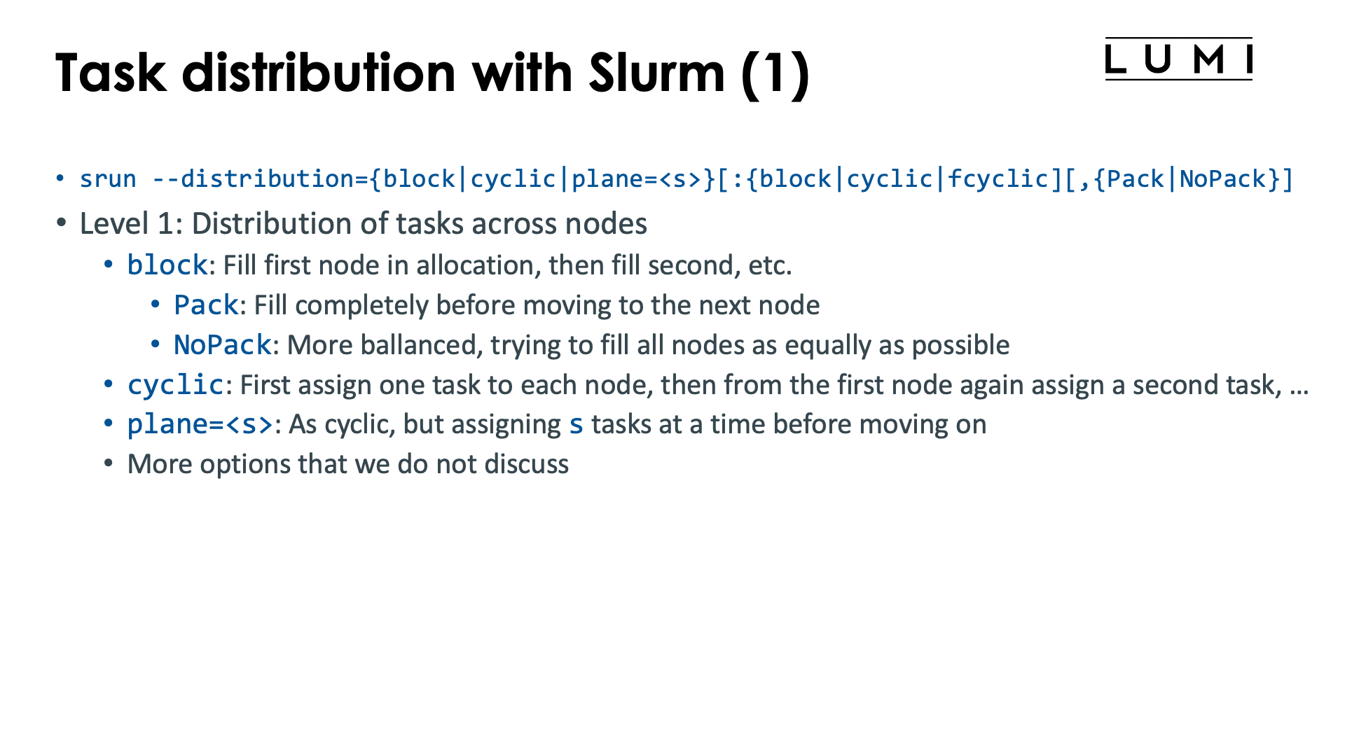
The Slurm srun command offers the --distribution option to influence the distribution of
tasks across nodes (level 1), sockets or NUMA domains (level 2 and sockets or NUMA) or
even across cores in the socket or NUMA domain (third level). The first level is the most useful level,
the second level is sometimes used but the third level is very tricky and both the second and third level
are often better replaced with other mechanisms that will also be discussed in this chapter on distribution
and binding.
The general form of the --distribution option is
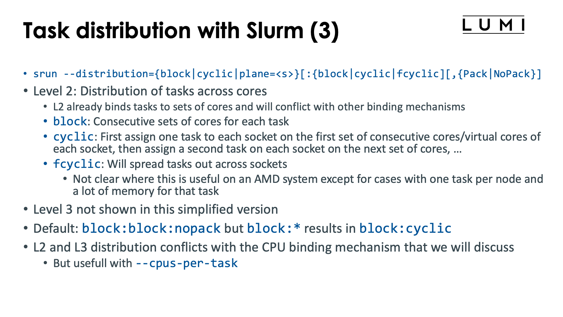
--distribution={*|block|cyclic|arbitrary|plane=<size>}[:{*|block|cyclic|fcyclic}[:{*|block|cyclic|fcyclic}]][,{Pack|NoPack}]
-
Level 1: Distribution across nodes. There are three useful options for LUMI:
-
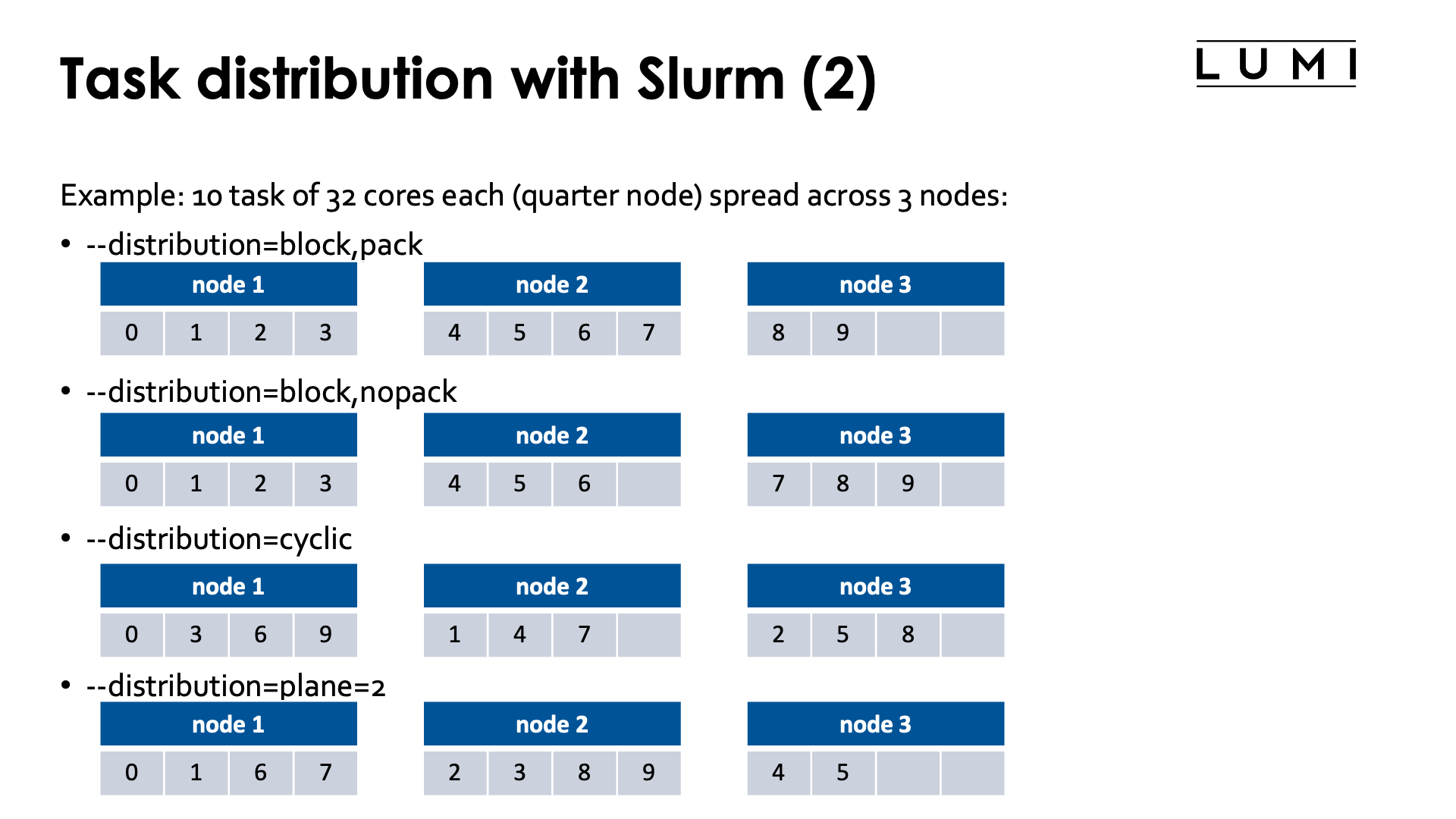
blockwhich is the default: A number of consecutive tasks is allocated on the first node, then another number of consecutive tasks on the second node, and so on till the last node of the allocation. Not all nodes may have the same number of tasks and this is determined by the optionalpackornopackparameter at the end.-
With
packthe first node in the allocation is first filled up as much as possible, then the second node, etc.E.g., with 10 quarter node sized tasks (32 cores on LUMI-C) spread across 3 nodes, this option would put tasks 0, 1, 2 and 3 on the first node, tasks 4, 5, 6 and 7 on the second node, and tasks 8 and 9 on the third (tasks are numbered from 0).
-
With
nopacka more balanced approach is taken filling up all nodes as equally as possible. In fact, the number of tasks on each node will correspond to that of thecyclicdistribution, but the task numbers will be different.E.g., with 10 quarter node tasks (32 cores on LUMI-C) spread across 3 nodes, this option would put tasks 0, 1, 2 and 3 on the first node, 4, 5 and 6 on the second and 7, 8 and 9 on the third.
-
-
cyclicassigns the tasks in a round-robin fashion to the nodes of the allocation. The first task is allocated to the first node, then the second one to the second node, and so on, and when all nodes of the allocation have received one task, the next one will be allocated again on the first node.E.g., with 10 quarter node tasks (32 cores on LUMI-C) spread across 3 nodes, task 0 would be put on the first node, task 1 on the second, task 2 on the third, task 3 again on the first node, etc., resulting in tasks 0, 3, 6 and 9 on the first node, tasks 1, 4 and 7 on the second node and tasks 2, 5 and 8 on the third node.
-
plane=<size>is a combination of both of the former methods: Blocks of<size>consecutive tasks are allocated in a cyclic way.E.g., with 10 quarter node tasks (32 cores on LUMI-C) spread across 3 nodes, task 0 and 1 would be put on the first node, then tasks 2 and 3 on the second, tasks 4 and 5 on the third, tasks 6 and 7 again on the first and finally tasks 8 and 9 on the second node, resulting in tasks 0, 1, 6 and 7 on the first node, tasks 2, 3, 8 and 9 on the second node and tasks 4 and 5 on the third node.
-
-
Level 2: Here we are distributing and pinning the tasks assigned to a node at level 1 across the sockets and cores of that node.
As this option already does a form of binding, it may conflict with other options that we will discuss later that also perform binding. In practice, this second level is less useful as often other mechanisms will be preferred for doing a proper binding, or the default behaviour is OK for simple distribution problems.
-
blockwill assign whole tasks to consecutive sets of cores on the node. On LUMI-C, it will first fill up the first socket before moving on to the second socket. -
cyclicassigns the first task of a node to a set of consecutive cores on the first socket, then the second task to a set of cores on the second socket, etc., in a round-robin way. It will do its best to not allocate tasks across sockets. -
fcyclicis a very strange distribution, where tasks requesting more than 1 CPU per task will see those spread out across sockets.We cannot see how this is useful on an AMD CPU except for cases where we have only one task per node which accesses a lot of memory (more than offered by a single socket) but does so in a very NUMA-aware way.
-
-
Level 3 is beyond the scope of an introductory course and rarely used.
The default behaviour of Slurm depends on LUMI seems to be block:block,nopack if --distribution is not specified,
though it is best to always verify as it can change over time and as the manual indicates that the
default differs according to the number of tasks compared to the number of nodes.
The defaults are also very tricky if a binding option at level 2 (or 3) is replaced with a * to mark
the default behaviour, e.g., --distribution="block:*" gives the result of --distribution=block:cyclic
while --distribution=block has the same effect as --distribution=block:block.
This option only makes sense on job-exclusive nodes.
Task-to-CPU binding with Slurm

In the Session on the LUMI architecture, we've seen that a LUMI compute node has a very hierarchical structure with 8 L3 cache domains per socket (the CCDs), each socket basically subdivided in 4 NUMA domains, and 2 sockets in the CPU nodes. The GPU nodes added further complexity: Each GPU is really two GCDs that should be treated as independent GPUs for most practical issues, except that, e.g., power cap is per package and not per GCD. Moreover, each GCD has its favoured CCD to which it is connected, and these connections can be important to get good performance of CPU-to-GPU communication. And each LUMI-G node also has 4 network interface cards, each connected to a separate GPU, so each CCD and each GCD also has a "best network interface" to maximise inter-node communication.
For these reasons, it is often important to distribute tasks and threads correctly over the system. And unfortunately, there is no way that works best for every application and every scenario.
For example, for memory performance reasons, you may want to bundle all threads of a task in a single L3 cache domain, a single NUMA domain or a single socket. In a hybrid MPI/OpenMP application it may be interesting to size each task to an L3 cache domain or a NUMA node for optimal performance. And for very memory bandwidth intensive applications, underpopulating cores may actually give you better performance for the same number of nodes, but then you need to carefully select the cores that will remain unpopulated to benefit most from cache and memory bandwidth.
In some cases, you may have a shared memory code that is very NUMA-aware but cannot use all cores efficiently because of memory bandwidth requirements or memory capacity requirements (simply needing more GB per core than LUMI can provide). In this case, you may want to spread out the threads as much as possible to have a maximal memory bandwidth.
On LUMI-G, proper mapping of CCDs, GCDs and network interfaces can be very important for good performance. The easiest way here is often to reorder the tasks across the CCDs in a non-trivial way to have an easy way to select the GPU for each task.

The level 2 and 3 options from the previous section already do some binding. But we will now discuss a different option that enables very precise binding of tasks to hardware threads in Slurm.
The mechanism does conflict with some Slurm options that implicitly already do some binding, e.g.,
it will not always work together with --cpus-per-task and --hint=[no]multithread may also not
act as expected depending on how the options are used.
Level 2 and 3 control via --distribution sometimes also makes no sense when this option is used
(and will be ignored).
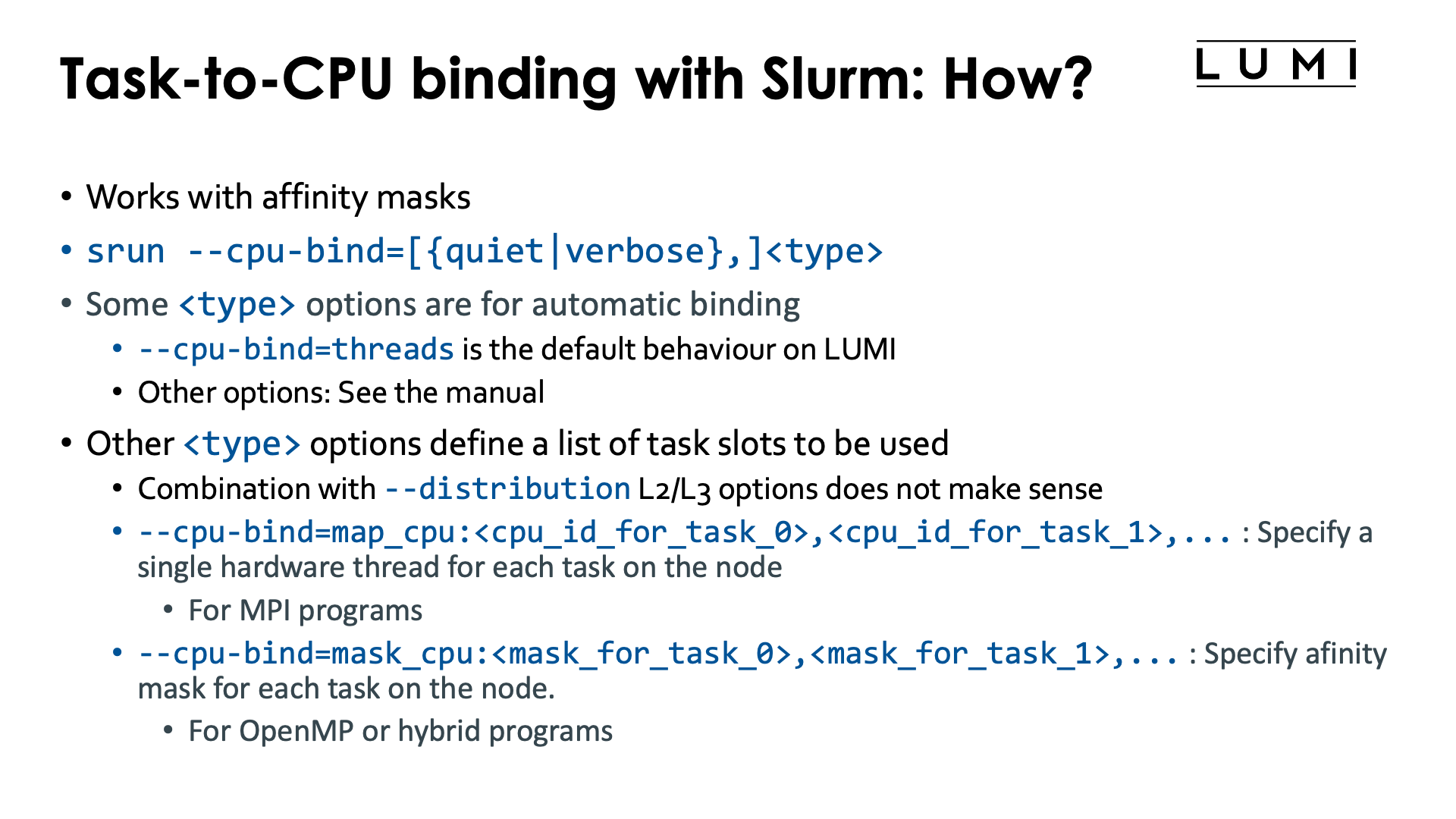
Task-to-CPU binding is controlled through the Slurm option
--cpu-bind=[{quiet|verbose},]<type>
We'll describe a few of the possibilities for the <type> parameter but for a more concrete overview
we refer to the Slurm srun manual page
-
--cpu-bind=threadsis the default behaviour on LUMI. Tasks will be allocated a number of hardware threads and be bound to them. -
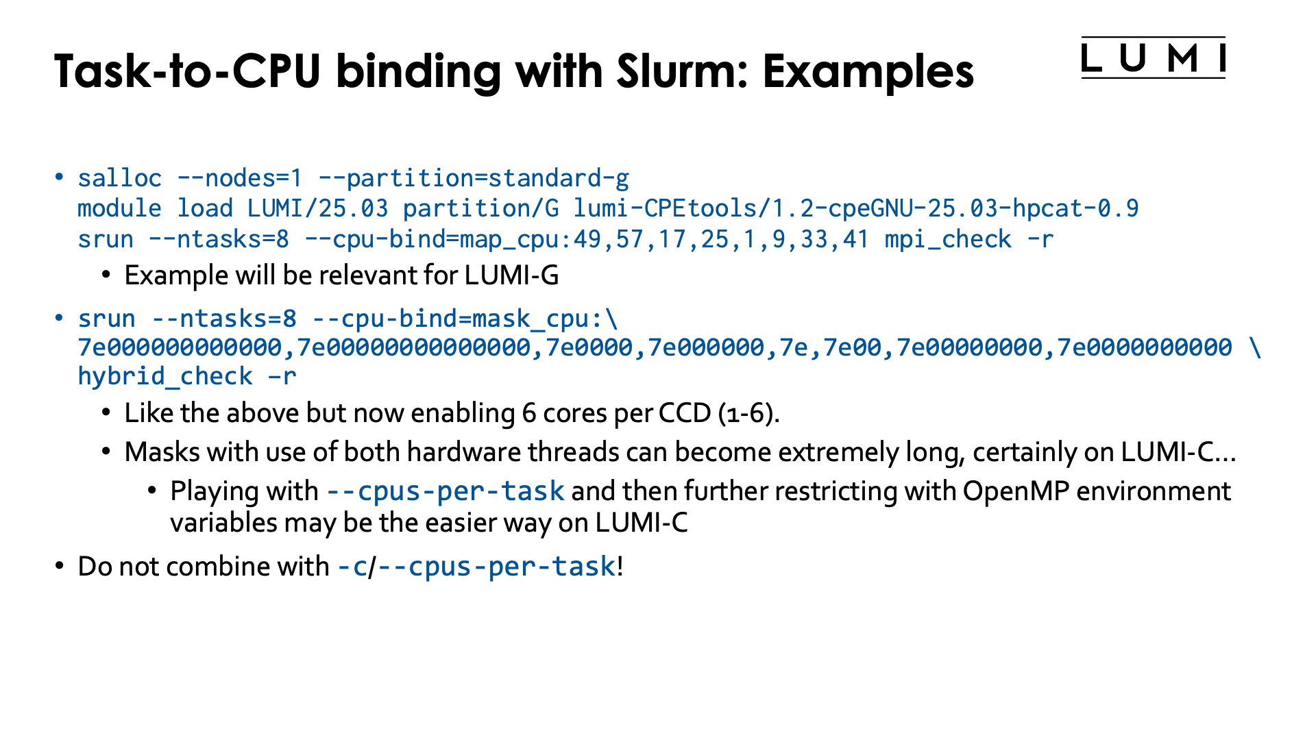
--cpu-bind=map_cpu:<cpu_id_for_task_0>,<cpu_id_for_task_1>, ...is used when tasks are bound to single cores. The first number is the number of the hardware thread for the task with local task ID 0, etc. In other words, this option at the same time also defines the slots that can be used by the--distributionoption above and replaces level 2 and level 3 of that option.E.g.,
salloc --nodes=1 --partition=standard-g
module load LUMI/24.03 partition/G lumi-CPEtools/1.2a-cpeGNU-24.03
srun --ntasks=8 --cpu-bind=map_cpu:49,57,17,25,1,9,33,41 mpi_check -r
will run the first task on hardware threads 49, the second task on 57, third on 17, fourth on 25, fifth on 1, sixth on 9, seventh on 33 and eight on 41.
This may look like a very strange numbering, but we will see an application for it further in this chapter.
-
--cpu-bind=mask_cpu:<mask_for_task_0>,<mask_for_task_1>,...is similar tomap_cpu, but now multiple hardware threads can be specified per task through a mask. The mask is a hexadecimal number and leading zeros can be omitted. The least significant bit in the mask corresponds to HWT 0, etc.Masks can become very long, but we shall see that this option is very useful on the nodes of the
standard-gpartition. Just as withmap_cpu, this option replaces level 2 and 3 of the--distributionoption.E.g.,
salloc --nodes=1 --partition=standard-g
module load LUMI/24.03 partition/G lumi-CPEtools/1.2a-cpeGNU-24.03
srun --ntasks=8 --cpu-bind=mask_cpu:7e000000000000,7e00000000000000,7e0000,7e000000,7e,7e00,7e00000000,7e0000000000 hybrid_check -r
will run the first task on hardware threads 49-54, the second task on 57-62, third on 17-22, fourth on 25-30, fifth on 1-6, sixth on 9-14, seventh on 33-38 and eight on 41-46.
The --cpu-bind=map_cpu and --cpu-bind=mask_gpu options also do not go together with -c / --cpus-per-task.
Both commands define a binding (the latter in combination with the default --cpu-bind=threads)
and these will usually conflict.
There are more options, but these are currently most relevant ones on LUMI. That may change in the future as LUMI User Support is investigating whether it isn't better to change the concept of "socket" in Slurm given how important it sometimes is to carefully map onto L3 cache domains for performance.
How to understand masks? (Click to expand)
Masks indicate which (virtual) cores can be used. A mask is really a series of bits with each bit corresponding to a virtual core. The least significant bit corresponds to core 0, the next one to core 1, etc. A 1-bit indicates that the corresponding virtual core can be used while a 0-bit indicates that it cannot be used.
Consider the mask 1111000001011010. For readability, we split it up in groups of 4
from right to left (and read vertically for the core numbers):
| Core | 1111 1100 0000 0000 5432 1098 7654 3210 |
| Mask | 1111 0000 0101 1010 |
Hence this masks indicates that cores 1, 3, 4, 6, 12, 13, 14 and 15 can be used.
Now using such long bit strings is awkward. There is a long tradition among computer scientists to represent such bit strings instead as hexadecimal numbers: numbers base 16, instead of as bit strings, numbers base 2. Each hexadecimal digit then corresponds with 4 bits, and we start assigning those again from the 4 least significant bits to the most significant bits, adding 0s at the front to get a multiple of 4 bits. The conversion is given by the following table.
| decimal | binary | hexadecimal |
| 0 | 0000 | 0 |
| 1 | 0001 | 1 |
| 2 | 0010 | 2 |
| 3 | 0011 | 3 |
| 4 | 0100 | 4 |
| 5 | 0101 | 5 |
| 6 | 0110 | 6 |
| 7 | 0111 | 7 |
| 8 | 1000 | 8 |
| 9 | 1001 | 9 |
| 10 | 1010 | a |
| 11 | 1011 | b |
| 12 | 1100 | c |
| 13 | 1101 | d |
| 14 | 1110 | e |
| 15 | 1111 | f |
So our mask 1111000001011010 is more conveniently written as f05a or F05A:
| Core | 1111 1100 0000 0000 5432 1098 7654 3210 |
| Mask | 1111 0000 0101 1010 |
| Hexadecimal | f 0 5 a |
To indicate that a number is a hexadecimal number, there are several conventions, but the
one which is usually used, is preceding the number with 0x, so our mask then becomes
0xf05a. This convention is used by bash and can also be used in Slurm masks.
Since CCDs on the zen3-based LUMI CPUs have 8 cores, they correspond to exactly 2 hexadecimal digits. This also implies that if we want to use the same cores on each CCD, building the mask becomes simple as we only need to look at CCD 0 and then shift the pattern two positions for each subsequent CCD.
The primary use case for all this will be core mapping on the GPU nodes to get an optimal binding between the cores and GCDs used by a Slurm task / MPI rank. On each CCD of a LUMI-G processor, core 0 cannot be used by the user. So building a mask that includes the first hardware thread of all available cores (cores 1-7) of a CCD is done as follows:
| Core | 7654 3210 |
| Mask | 1111 1110 |
| Hexadecimal | f e |
so the mask is 0xfe. Suppose that we want to use all 7 available cores on CCD 1, i.e., cores 9 till 15,
we get
| Core | 1111 1100 0000 0000 5432 1098 7654 3210 |
| Mask | 1111 1110 0000 0000 |
| Hexadecimal | f e 0 0 |
of 0xfe00, so really just our pattern for CCD 0 shifted by two positions by adding two
zeros at the end.
For the example above, with
--cpu-bind=mask_cpu:7e000000000000,7e00000000000000,7e0000,7e000000,7e,7e00,7e00000000,7e0000000000,
the basic building block is 0x7e, so
| Hexadecimal | 7 e |
| Mask | 0111 1110 |
| Core | 7654 3210 |
or cores 1 till 6. For the whole mask, we get:
| CCD | 7 6 5 4 3 2 1 0 | using |
| Element 1 | 7e 00 00 00 00 00 00 | CCD 6, cores 49-54 |
| Element 2 | 7e 00 00 00 00 00 00 00 | CCD 7, cores 57-62 |
| Element 3 | 7e 00 00 | CCD 2, cores 17-22 |
| Element 4 | 7e 00 00 00 | CCD 3, cores 25-30 |
| Element 5 | 7e | CCD 0, cores 1-6 |
| Element 6 | 7e 00 | CCD 1, cores 9-14 |
| Element 7 | 7e 00 00 00 00 | CCD 4, cores 33-38 |
| Element 1 | 7e 00 00 00 00 00 | CCD 5, cores 41-46 |
So basically this mask means that we are creating slots for 8 tasks that each use 6 cores on a single CCD (cores 1 till 6), in the order CCD 6, CCD 7, CCD 2, CCD 3, CCD 0, CCD 1, CCD 4 and CCD 5.
Task-to-GPU binding with Slurm

Be very careful when doing the task-to-GPU binding fully via Slurm.
The problem is that Slurm by default uses control groups at the task level rather than just ROCR_VISIBLE_DEVICES
with the latter being more or less the equivalent of affinity masks. When using control groups this way,
the other GPUs in a job step on a node become completely invisible to a task, and the
Peer2Peer IPC mechanism for communication cannot be used anymore.
So you should always combine this with --gres-flags=task-sharing.
We present the options for completeness, and as it may still help users if the control group setup is not a problem for the application.
Task-to-GPU binding is done with
--gpu-bind=[verbose,]<type>
(see the Slurm manual)
which is somewhat similar to --cpu-binding (to the extent that that makes sense).
Some options for the <type> parameter that are worth considering:
-
--gpu-bind=closest: This currently does not work well on LUMI. The problem is being investigated so the situation may have changed by the time you read this. -
--gpu-bind=none: Turns off the GPU binding of Slurm. This can actually be useful on shared node jobs where doing a proper allocation of GPUs is difficult. You can then first use Slurm options such as--gpus-per-taskto get a working allocation of GPUs and CPUs, then un-bind and rebind using a different mechanism that we will discuss later. -
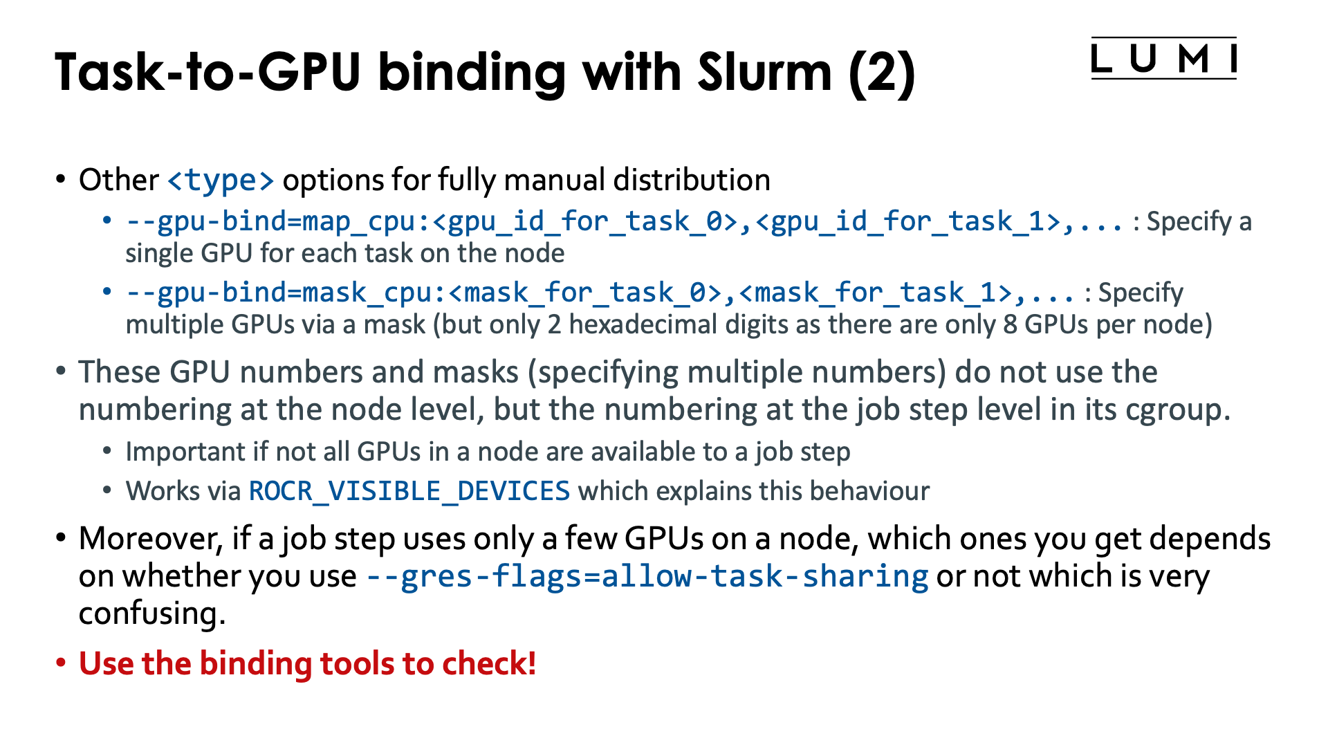
--gpu-bind=map_gpu:<list>is the equivalent of--cpu-bind=map_cpu:<list>. This option only makes sense on a job-exclusive node and is for jobs that need a single GPU per task. It defines the list of GPUs that should be used, with the task with local ID 0 using the first one in the list, etc. The numbering and topology was already discussed in the "LUMI Architecture" chapter, section "Building LUMI: What a LUMI-G really looks like. -
--gpu-bind=mask_gpu:<list>is the equivalent of--cpu-bind=mask_cpu:<list>. Now the bits in the mask correspond to individual GPUs, with GPU 0 the least significant bit. This option again only makes sense on a job-exclusive node.
Though map_gpu and mask_gpu could be very useful to get a proper mapping taking the topology of the
node into account, due to the current limitation of creating a control group per task it can not often
be used as it breaks some efficient communication mechanisms between tasks, including the GPU Peer2Peer
IPC used by Cray MPICH for intro-node MPI transfers if GPU aware MPI support is enabled.
What do the HPE Cray manuals say about this? (Click to expand)
From the HPE Cray CoE:
"Slurm may choose to use cgroups to implement the required
affinity settings. Typically, the use of cgroups has the downside of preventing the use of
GPU Peer2Peer IPC mechanisms. By default Cray MPI uses IPC for
implementing intra-node, inter-process MPI data movement operations that involve GPU-attached user buffers.
When Slurm’s cgroups settings are in effect, users are
advised to set MPICH_SMP_SINGLE_COPY_MODE=NONE or MPICH_GPU_IPC_ENABLED=0
to disable the use of IPC-based implementations.
Disabling IPC also has a noticeable impact on intra-node MPI performance when
GPU-attached memory regions are involved."
This is exactly what Slurm does on LUMI unless --gres-flags=task-sharing
is used.
Playing around with --gpu-bind (click to expand)
Consider the following script which is a variant of scripts used before in this chapter of the tutorial.
#!/bin/bash
#SBATCH --job-name=gpubind-demo1
#SBATCH --output %x-%j.txt
#SBATCH --account=project_46YXXXXXX
#SBATCH --partition=standard-g
#SBATCH --nodes=1
#SBATCH --hint=nomultithread
#SBATCH --time=15:00

module load LUMI/25.03 partition/G systools/25.03-2 lumi-CPEtools/1.2-cpeGNU-25.03-hpcat-0.9

cat << EOF > task_lstopo_$SLURM_JOB_ID
#!/bin/bash
echo "Task \$SLURM_LOCALID"                                                              > output-\$SLURM_JOB_ID-\$SLURM_LOCALID
echo "Relevant lines of lstopo:"                                                         >> output-\$SLURM_JOB_ID-\$SLURM_LOCALID
lstopo -p | awk '/ PCI.*Display/ || /GPU/ || /OpenCL/ || / Core / || /PU L/ {print \$0}' >> output-\$SLURM_JOB_ID-\$SLURM_LOCALID
echo "GPUs as found by rocm-smi:"                                                        >> output-\$SLURM_JOB_ID-\$SLURM_LOCALID
rocm-smi --showbus                                                                       >> output-\$SLURM_JOB_ID-\$SLURM_LOCALID
echo "ROCR_VISIBLE_DEVICES: \$ROCR_VISIBLE_DEVICES"                                      >> output-\$SLURM_JOB_ID-\$SLURM_LOCALID
EOF
chmod +x ./task_lstopo_$SLURM_JOB_ID

echo "Overview of CCD-to-GPU binding in the node:"
lstopo -p | awk '/ L3 P/ || / PCI.*Display/ || /GPU/ {print \$0}'

echo -e "\nRunning two tasks with 2 GPUs each with -G 4, extracting parts from lstopo output in each:"
srun -n 2 -c 1 -G 4 --gpu-bind=mask_gpu:0x3,0xc ./task_lstopo_$SLURM_JOB_ID
echo
cat output-$SLURM_JOB_ID-0
echo
cat output-$SLURM_JOB_ID-1

sleep 2

echo -e "\nRunning gpu_check in the same configuration:"
srun -n 2 -c 1 -G 4 --gpu-bind=mask_gpu:0x3,0xc gpu_check -l

sleep 2

echo -e "\nRunning two tasks with 2 GPUs each with -G 4, now with --gres-flags=allow-task-sharing, extracting parts from lstopo output in each:"
srun -n 2 -c 1 -G 4 --gpu-bind=mask_gpu:0x3,0xc --gres-flags=allow-task-sharing ./task_lstopo_$SLURM_JOB_ID
echo
cat output-$SLURM_JOB_ID-0
echo
cat output-$SLURM_JOB_ID-1

sleep 2

echo -e "\nRunning gpu_check in the same configuration with --gres-flags=allow-task-sharing:"
srun -n 2 -c 1 -G 4 --gpu-bind=mask_gpu:0x3,0xc --gres-flags=allow-task-sharing gpu_check -l

sleep 2

echo -e "\nRunning two tasks with 2 GPUs each with -G 8, now with --gres-flags=allow-task-sharing, extracting parts from lstopo output in each:"
srun -n 2 -c 1 -G 8 --gpu-bind=mask_gpu:0x3,0xc --gres-flags=allow-task-sharing ./task_lstopo_$SLURM_JOB_ID
echo
cat output-$SLURM_JOB_ID-0
echo
cat output-$SLURM_JOB_ID-1

sleep 2

echo -e "\nRunning gpu_check in the same configuration with --gres-flags=allow-task-sharing:"
srun -n 2 -c 1 -G 8 --gpu-bind=mask_gpu:0x3,0xc --gres-flags=allow-task-sharing gpu_check -l

/bin/rm task_lstopo_$SLURM_JOB_ID output-$SLURM_JOB_ID-0 output-$SLURM_JOB_ID-1
Let us first check the output for the two first srun commands:
Task 0
Relevant lines of lstopo:
    L2 P#1 (512KB) + L1d P#1 (32KB) + L1i P#1 (32KB) + Core P#1
        PCI d1:00.0 (Display)
          GPU(RSMI) "rsmi0"
          CoProc(OpenCL) "opencl0d0"
    L2 P#9 (512KB) + L1d P#9 (32KB) + L1i P#9 (32KB) + Core P#9
        PCI d6:00.0 (Display)
          GPU(RSMI) "rsmi1"
          CoProc(OpenCL) "opencl0d1"
        PCI c9:00.0 (Display)
        PCI ce:00.0 (Display)
        PCI d9:00.0 (Display)
        PCI de:00.0 (Display)
        PCI c1:00.0 (Display)
        PCI c6:00.0 (Display)
GPUs as found by rocm-smi:
============================ ROCm System Management Interface ============================
======================================= PCI Bus ID =======================================
GPU[0]      : PCI Bus: 0000:D1:00.0
GPU[1]      : PCI Bus: 0000:D6:00.0
==========================================================================================
================================== End of ROCm SMI Log ===================================
ROCR_VISIBLE_DEVICES: 0,1

Task 1
Relevant lines of lstopo:
    L2 P#1 (512KB) + L1d P#1 (32KB) + L1i P#1 (32KB) + Core P#1
        PCI d1:00.0 (Display)
    L2 P#9 (512KB) + L1d P#9 (32KB) + L1i P#9 (32KB) + Core P#9
        PCI d6:00.0 (Display)
        PCI c9:00.0 (Display)
          GPU(RSMI) "rsmi0"
          CoProc(OpenCL) "opencl0d0"
        PCI ce:00.0 (Display)
          GPU(RSMI) "rsmi1"
          CoProc(OpenCL) "opencl0d1"
        PCI d9:00.0 (Display)
        PCI de:00.0 (Display)
        PCI c1:00.0 (Display)
        PCI c6:00.0 (Display)
GPUs as found by rocm-smi:
============================ ROCm System Management Interface ============================
======================================= PCI Bus ID =======================================
GPU[0]      : PCI Bus: 0000:C9:00.0
GPU[1]      : PCI Bus: 0000:CE:00.0
==========================================================================================
================================== End of ROCm SMI Log ===================================
ROCR_VISIBLE_DEVICES: 0,1

Running gpu_check in the same configuration:
MPI 000 - OMP 000 - HWT 001 (CCD0) - Node nid005416 - RT_GPU_ID 0,1 - GPU_ID 0,1 - Bus_ID d1(GCD4/CCD0),d6(GCD5/CCD1)
MPI 001 - OMP 000 - HWT 009 (CCD1) - Node nid005416 - RT_GPU_ID 0,1 - GPU_ID 0,1 - Bus_ID c9(GCD2/CCD2),ce(GCD3/CCD3)
From the mask, we would expect that the first task gets the GPUs rsmi0 and rsmi1 in
the node-global numbering and the second task then gets rsmi2 and rsmi3 in that numbering,
but this is not what is happening here. Instead, task 0 gets GCD 4 and 5, attached to CCD 0 and 1
respectively but task 2 does get GCD2 and 3, but probably only because these happen to be
attached to CCD 2 and 3.
ROCR_VISIBLE_DEVICES is for both tasks set to 0,1 as it uses the numbering within
the task-based cgroups.
When we run with --gres-flags=allow-sharing but still using -G 4, the result is different though:
Task 0
Relevant lines of lstopo:
    L2 P#1 (512KB) + L1d P#1 (32KB) + L1i P#1 (32KB) + Core P#1
        PCI d1:00.0 (Display)
          GPU(RSMI) "rsmi2"
    L2 P#9 (512KB) + L1d P#9 (32KB) + L1i P#9 (32KB) + Core P#9
        PCI d6:00.0 (Display)
          GPU(RSMI) "rsmi3"
        PCI c9:00.0 (Display)
          GPU(RSMI) "rsmi0"
          CoProc(OpenCL) "opencl0d0"
        PCI ce:00.0 (Display)
          GPU(RSMI) "rsmi1"
          CoProc(OpenCL) "opencl0d1"
        PCI d9:00.0 (Display)
        PCI de:00.0 (Display)
        PCI c1:00.0 (Display)
        PCI c6:00.0 (Display)
GPUs as found by rocm-smi:
============================ ROCm System Management Interface ============================
======================================= PCI Bus ID =======================================
GPU[0]      : PCI Bus: 0000:C9:00.0
GPU[1]      : PCI Bus: 0000:CE:00.0
GPU[2]      : PCI Bus: 0000:D1:00.0
GPU[3]      : PCI Bus: 0000:D6:00.0
==========================================================================================
================================== End of ROCm SMI Log ===================================
ROCR_VISIBLE_DEVICES: 0,1

Task 1
Relevant lines of lstopo:
    L2 P#1 (512KB) + L1d P#1 (32KB) + L1i P#1 (32KB) + Core P#1
        PCI d1:00.0 (Display)
          GPU(RSMI) "rsmi2"
          CoProc(OpenCL) "opencl0d0"
    L2 P#9 (512KB) + L1d P#9 (32KB) + L1i P#9 (32KB) + Core P#9
        PCI d6:00.0 (Display)
          GPU(RSMI) "rsmi3"
          CoProc(OpenCL) "opencl0d1"
        PCI c9:00.0 (Display)
          GPU(RSMI) "rsmi0"
        PCI ce:00.0 (Display)
          GPU(RSMI) "rsmi1"
        PCI d9:00.0 (Display)
        PCI de:00.0 (Display)
        PCI c1:00.0 (Display)
        PCI c6:00.0 (Display)
GPUs as found by rocm-smi:
============================ ROCm System Management Interface ============================
======================================= PCI Bus ID =======================================
GPU[0]      : PCI Bus: 0000:C9:00.0
GPU[1]      : PCI Bus: 0000:CE:00.0
GPU[2]      : PCI Bus: 0000:D1:00.0
GPU[3]      : PCI Bus: 0000:D6:00.0
==========================================================================================
================================== End of ROCm SMI Log ===================================
ROCR_VISIBLE_DEVICES: 2,3

Running gpu_check in the same configuration with --gres-flags=allow-task-sharing:
MPI 000 - OMP 000 - HWT 001 (CCD0) - Node nid005322 - RT_GPU_ID 0,1 - GPU_ID 0,1 - Bus_ID c9(GCD2/CCD2),ce(GCD3/CCD3)
MPI 001 - OMP 000 - HWT 009 (CCD1) - Node nid005322 - RT_GPU_ID 0,1 - GPU_ID 2,3 - Bus_ID d1(GCD4/CCD0),d6(GCD5/CCD1)
lstopo or rocm-smi --showbus now sees the same 4 GPUs in each task, and these are actually
GCD2, GCD3, GCD4 and GCD5 rather than GCD 0 till GCD3, i.e., we get the GCDs attached to CCD 0 till 3.
These are then renumberd in the order GCD2, GCD3, GCD4, GCD5 to rsmi0 till rsmi3
which follows the order in the physical numbering and not the order of the CCDs.
Both tasks get a different
value of ROCR_VISIBLE_DEVICES corresponding to the values in the mask: The first task
get 0,1 which corresponds to 0x3 and the second task gets 2,3 which corresponds to
0xc. These are GPUs within the numbering in the Slurm jobstep though and not the physical
numbering of the GPUs. It does result in a different mapping though than when we were not
using the --gres-flags option as the numbering is now relative to the GPU numbering in the
job step based cgroup.
Finally, when we allow the job step access to all GPUs with -G 8 but then restrict
the GPUs per task with the same masks as before, we now get:
Task 0
Relevant lines of lstopo:
    L2 P#1 (512KB) + L1d P#1 (32KB) + L1i P#1 (32KB) + Core P#1
        PCI d1:00.0 (Display)
          GPU(RSMI) "rsmi4"
    L2 P#9 (512KB) + L1d P#9 (32KB) + L1i P#9 (32KB) + Core P#9
        PCI d6:00.0 (Display)
          GPU(RSMI) "rsmi5"
        PCI c9:00.0 (Display)
          GPU(RSMI) "rsmi2"
        PCI ce:00.0 (Display)
          GPU(RSMI) "rsmi3"
        PCI d9:00.0 (Display)
          GPU(RSMI) "rsmi6"
        PCI de:00.0 (Display)
          GPU(RSMI) "rsmi7"
        PCI c1:00.0 (Display)
          GPU(RSMI) "rsmi0"
          CoProc(OpenCL) "opencl0d0"
        PCI c6:00.0 (Display)
          GPU(RSMI) "rsmi1"
          CoProc(OpenCL) "opencl0d1"
GPUs as found by rocm-smi:
============================ ROCm System Management Interface ============================
======================================= PCI Bus ID =======================================
GPU[0]      : PCI Bus: 0000:C1:00.0
GPU[1]      : PCI Bus: 0000:C6:00.0
GPU[2]      : PCI Bus: 0000:C9:00.0
GPU[3]      : PCI Bus: 0000:CE:00.0
GPU[4]      : PCI Bus: 0000:D1:00.0
GPU[5]      : PCI Bus: 0000:D6:00.0
GPU[6]      : PCI Bus: 0000:D9:00.0
GPU[7]      : PCI Bus: 0000:DE:00.0
==========================================================================================
================================== End of ROCm SMI Log ===================================
ROCR_VISIBLE_DEVICES: 0,1

Task 1
Relevant lines of lstopo:
    L2 P#1 (512KB) + L1d P#1 (32KB) + L1i P#1 (32KB) + Core P#1
        PCI d1:00.0 (Display)
          GPU(RSMI) "rsmi4"
    L2 P#9 (512KB) + L1d P#9 (32KB) + L1i P#9 (32KB) + Core P#9
        PCI d6:00.0 (Display)
          GPU(RSMI) "rsmi5"
        PCI c9:00.0 (Display)
          GPU(RSMI) "rsmi2"
          CoProc(OpenCL) "opencl0d0"
        PCI ce:00.0 (Display)
          GPU(RSMI) "rsmi3"
          CoProc(OpenCL) "opencl0d1"
        PCI d9:00.0 (Display)
          GPU(RSMI) "rsmi6"
        PCI de:00.0 (Display)
          GPU(RSMI) "rsmi7"
        PCI c1:00.0 (Display)
          GPU(RSMI) "rsmi0"
        PCI c6:00.0 (Display)
          GPU(RSMI) "rsmi1"
GPUs as found by rocm-smi:
============================ ROCm System Management Interface ============================
======================================= PCI Bus ID =======================================
GPU[0]      : PCI Bus: 0000:C1:00.0
GPU[1]      : PCI Bus: 0000:C6:00.0
GPU[2]      : PCI Bus: 0000:C9:00.0
GPU[3]      : PCI Bus: 0000:CE:00.0
GPU[4]      : PCI Bus: 0000:D1:00.0
GPU[5]      : PCI Bus: 0000:D6:00.0
GPU[6]      : PCI Bus: 0000:D9:00.0
GPU[7]      : PCI Bus: 0000:DE:00.0
==========================================================================================
================================== End of ROCm SMI Log ===================================
ROCR_VISIBLE_DEVICES: 2,3

Running gpu_check in the same configuration with --gres-flags=allow-task-sharing:
MPI 000 - OMP 000 - HWT 001 (CCD0) - Node nid005416 - RT_GPU_ID 0,1 - GPU_ID 0,1 - Bus_ID c1(GCD0/CCD6),c6(GCD1/CCD7)
MPI 001 - OMP 000 - HWT 009 (CCD1) - Node nid005416 - RT_GPU_ID 0,1 - GPU_ID 2,3 - Bus_ID c9(GCD2/CCD2),ce(GCD3/CCD3)
Each task now sees all GPUs. ROCR_VISIBLE_DEVICES is again set to 0,1 for the first task
and to 2,3 for the second task, but as all GPUs are visible in the cgroup, this now sets
yet a different mapping: Task 0 is now mapped to GCD0 and 1 in the physical, node-global
numbering, while task 1 is now mapped to GCD2 and 3 in the physical, node-global numbering.
What this example shows is that when a job step does not use all GPUs on a node, even though it is an exclusive node, you have to be very careful as there is still a control group at the jobstep level restricting the job step to a number of GPUs and mask then refer to the numbering within that jobstep-specific control group.
This example shows that CPU binding and GPU binding works differently because the underlying
mechanisms work differently: CPU affinity masks work with absolute virtual core numbers, while
ROCR_VISIBLE_DEVICES works with a numbering that is based on the GPUs visible in the innermost
control group if not all GPUs are visible. The example also shows that the way Slurm assigns
GPUs on a node to a job step, differs depending on whether --gres-flags=allow-task-sharing
is used or not and that is confusing...
It shows that binding is very complex and that you should never assume you understand what Slurm does and instead whenever you change mappings, check those with the tools that we have made available if that is possible.
MPI rank redistribution with Cray MPICH

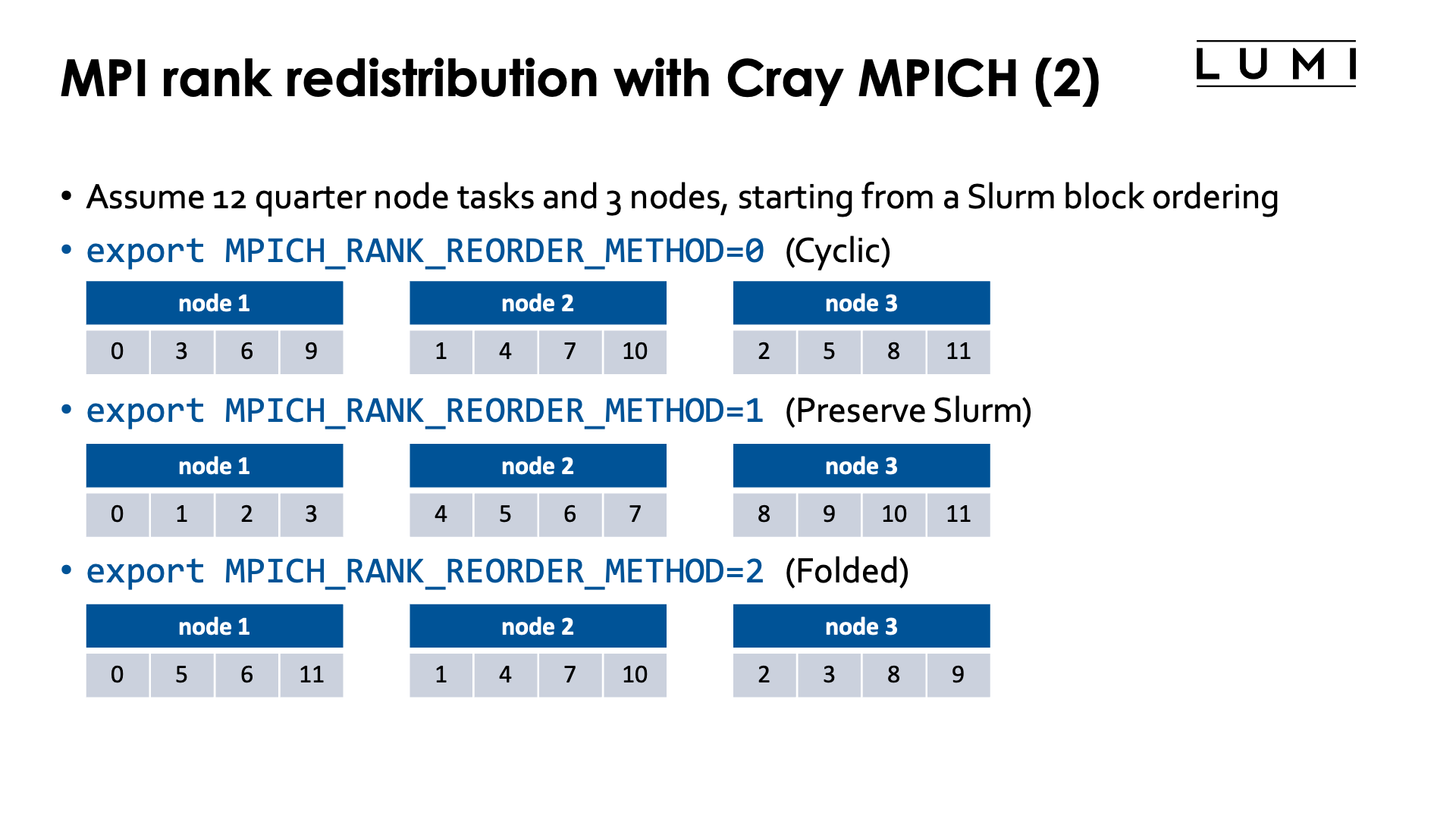
By default MPI rank i will use Slurm task i in a parallel job step.
With Cray MPICH this can be changed via the environment variable
MPICH_RANK_REORDER_METHOD. It provides an even more powerful way
of reordering MPI ranks than the Slurm --distribution option as one
can define fully custom orderings.
Rank reordering is an advanced topic that is discussed in more detail in the 4 or 5-day Advanced LUMI course or the "Performance Analysis and Optimization" workshop organised by the LUMI User Support Team. The material of the latest advanced course can be found via the course archive web page and is discussed in the "MPI Topics on the HPE Cray EX Supercomputer" which is often given on day 3.
Rank reordering can be used to reduce the number of inter-node messages or to spread those ranks that do parallel I/O over more nodes to increase the I/O bandwidth that can be obtained in the application.
Possible values for MPICH_RANK_REORDER_METHOD are:
-
export MPICH_RANK_REORDER_METHOD=0: Round-robin placement of the MPI ranks. This is the equivalent of the cyclic ordering in Slurm. -
export MPICH_RANK_REORDER_METHOD=1: This is the default and it preserves the ordering of Slurm, and the only one that makes sense with other L1 Slurm distributions thanblock.The Cray MPICH manual confusingly calls this "SMP-style ordering".
-
export MPICH_RANK_REORDER_METHOD=2: Folded rank placement. This is somewhat similar to round-robin, but when the last node is reached, the node list is transferred in the opposite direction. -
export MPICH_RANK_REORDER_METHOD=3: Use a custom ordering, given by theMPICH_RANK_ORDERfile which gives a comma-separated list of the MPI ranks in the order they should be assigned to slots on the nodes. The default filenameMPICH_RANK_ORDERcan be overwritten through the environment variableMPICH_RANK_REORDER_FILE.
Rank reordering does not always work well if Slurm is not using the (default) block ordering.
As the lumi-CPEtools mpi_check, hybrid_check and gpu_check commands use Cray MPICH
they can be used to test the Cray MPICH rank reordering also. The MPI ranks that are
displayed are the MPI ranks as seen through MPI calls and not the value of
SLURM_PROCID which is the Slurm task number.
The HPE Cray Programming Environment actually has profiling tools that help you determine the optimal rank ordering for a particular run, which is useful if you do a lot of runs with the same problem size (and hence same number of nodes and tasks).
Try the following job script (click to expand)
1 2 3 4 5 6 7 8 9 10 11 12 13 14 15 16 17 18 19 20 21 22 23 24 25 26 27 28 29 30 31 32 33 | |
Ths script starts 8 tasks that each take a quarter node.
-
The first
sruncommand (on line 15) is just the block distribution. The first 4 MPI ranks are on the first node, the next 4 on the second node.+ export MPICH_RANK_REORDER_METHOD=1 + MPICH_RANK_REORDER_METHOD=1 + srun -n 8 -c 32 -m block mpi_check -r Running 8 single-threaded MPI ranks. ++ mpi_check: MPI rank 0/8 host nid002183 cpu 1/256 mask (0-31) ++ mpi_check: MPI rank 1/8 host nid002183 cpu 32/256 mask (32-63) ++ mpi_check: MPI rank 2/8 host nid002183 cpu 64/256 mask (64-95) ++ mpi_check: MPI rank 3/8 host nid002183 cpu 112/256 mask (96-127) ++ mpi_check: MPI rank 4/8 host nid002184 cpu 0/256 mask (0-31) ++ mpi_check: MPI rank 5/8 host nid002184 cpu 32/256 mask (32-63) ++ mpi_check: MPI rank 6/8 host nid002184 cpu 64/256 mask (64-95) ++ mpi_check: MPI rank 7/8 host nid002184 cpu 111/256 mask (96-127) -
The second
sruncommand, on line 18, is an example where the Slurm cyclic distribution is preserved. MPI rank 0 now lands on the first 32 cores of node 0 of the allocation, MPI rank 1 on the first 32 cores of node 1 of the allocation, then task 2 on the second 32 cores of node 0, and so on:+ export MPICH_RANK_REORDER_METHOD=1 + MPICH_RANK_REORDER_METHOD=1 + srun -n 8 -c 32 -m cyclic mpi_check -r Running 8 single-threaded MPI ranks. ++ mpi_check: MPI rank 0/8 host nid002183 cpu 1/256 mask (0-31) ++ mpi_check: MPI rank 1/8 host nid002184 cpu 1/256 mask (0-31) ++ mpi_check: MPI rank 2/8 host nid002183 cpu 32/256 mask (32-63) ++ mpi_check: MPI rank 3/8 host nid002184 cpu 32/256 mask (32-63) ++ mpi_check: MPI rank 4/8 host nid002183 cpu 64/256 mask (64-95) ++ mpi_check: MPI rank 5/8 host nid002184 cpu 64/256 mask (64-95) ++ mpi_check: MPI rank 6/8 host nid002183 cpu 112/256 mask (96-127) ++ mpi_check: MPI rank 7/8 host nid002184 cpu 112/256 mask (96-127) -
The third
sruncommand, on line 21, uses Cray MPICH rank reordering instead to get a round-robin ordering rather than using the Slurm--distribution=cyclicoption. The result is the same as in the previous case:+ export MPICH_RANK_REORDER_METHOD=0 + MPICH_RANK_REORDER_METHOD=0 + srun -n 8 -c 32 -m block mpi_check -r Running 8 single-threaded MPI ranks. ++ mpi_check: MPI rank 0/8 host nid002183 cpu 0/256 mask (0-31) ++ mpi_check: MPI rank 1/8 host nid002184 cpu 0/256 mask (0-31) ++ mpi_check: MPI rank 2/8 host nid002183 cpu 63/256 mask (32-63) ++ mpi_check: MPI rank 3/8 host nid002184 cpu 32/256 mask (32-63) ++ mpi_check: MPI rank 4/8 host nid002183 cpu 64/256 mask (64-95) ++ mpi_check: MPI rank 5/8 host nid002184 cpu 64/256 mask (64-95) ++ mpi_check: MPI rank 6/8 host nid002183 cpu 120/256 mask (96-127) ++ mpi_check: MPI rank 7/8 host nid002184 cpu 113/256 mask (96-127) -
The fourth
sruncommand, on line 24, demonstrates the folded ordering: Rank 0 runs on the first 32 cores of node 0 of the allocation, rank 1 on the first 32 of node 1, then rank 2 runs on the second set of 32 cores again on node 1, with rank 3 then running on the second 32 cores of node 0, rank 4 on the third group of 32 cores of node 0, rank 5 on the third group of 32 cores on rank 1, and so on. So the nodes are filled in the order 0, 1, 1, 0, 0, 1, 1, 0.+ export MPICH_RANK_REORDER_METHOD=2 + MPICH_RANK_REORDER_METHOD=2 + srun -n 8 -c 32 -m block mpi_check -r Running 8 single-threaded MPI ranks. ++ mpi_check: MPI rank 0/8 host nid002183 cpu 0/256 mask (0-31) ++ mpi_check: MPI rank 1/8 host nid002184 cpu 0/256 mask (0-31) ++ mpi_check: MPI rank 2/8 host nid002184 cpu 32/256 mask (32-63) ++ mpi_check: MPI rank 3/8 host nid002183 cpu 32/256 mask (32-63) ++ mpi_check: MPI rank 4/8 host nid002183 cpu 64/256 mask (64-95) ++ mpi_check: MPI rank 5/8 host nid002184 cpu 64/256 mask (64-95) ++ mpi_check: MPI rank 6/8 host nid002184 cpu 112/256 mask (96-127) ++ mpi_check: MPI rank 7/8 host nid002183 cpu 114/256 mask (96-127) -
The fifth example ('srun' on line 31) demonstrate a custom reordering. Here we face a 4x2-grid which we want to split in 2 2x2 groups. So where the ranks in our grid are numbered as
0 1 2 3
4 5 6 7
we really want the left half of the grid on the first node of the allocation and the right half on the second node as this gives us less inter-node communication than when we would put the first line on the first node and the second line on the second. So basically we want ranks 0, 1, 4 and 5 on the first node and ranks 2, 3, 6 and 7 on the second node, which is done by creating the reorder file with content
0,1,4,5,2,3,6,7The resulting output is
+ export MPICH_RANK_REORDER_METHOD=3
+ MPICH_RANK_REORDER_METHOD=3
+ cat MPICH_RANK_ORDER
0,1,4,5,2,3,6,7
+ srun -n 8 -c 32 -m block mpi_check -r

Running 8 single-threaded MPI ranks.

++ mpi_check: MPI rank   0/8   host nid002183 cpu  17/256 mask (0-31)
++ mpi_check: MPI rank   1/8   host nid002183 cpu  32/256 mask (32-63)
++ mpi_check: MPI rank   2/8   host nid002184 cpu   0/256 mask (0-31)
++ mpi_check: MPI rank   3/8   host nid002184 cpu  32/256 mask (32-63)
++ mpi_check: MPI rank   4/8   host nid002183 cpu  64/256 mask (64-95)
++ mpi_check: MPI rank   5/8   host nid002183 cpu 113/256 mask (96-127)
++ mpi_check: MPI rank   6/8   host nid002184 cpu  64/256 mask (64-95)
++ mpi_check: MPI rank   7/8   host nid002184 cpu 113/256 mask (96-127)
MPI network adapter binding with Cray MPICH
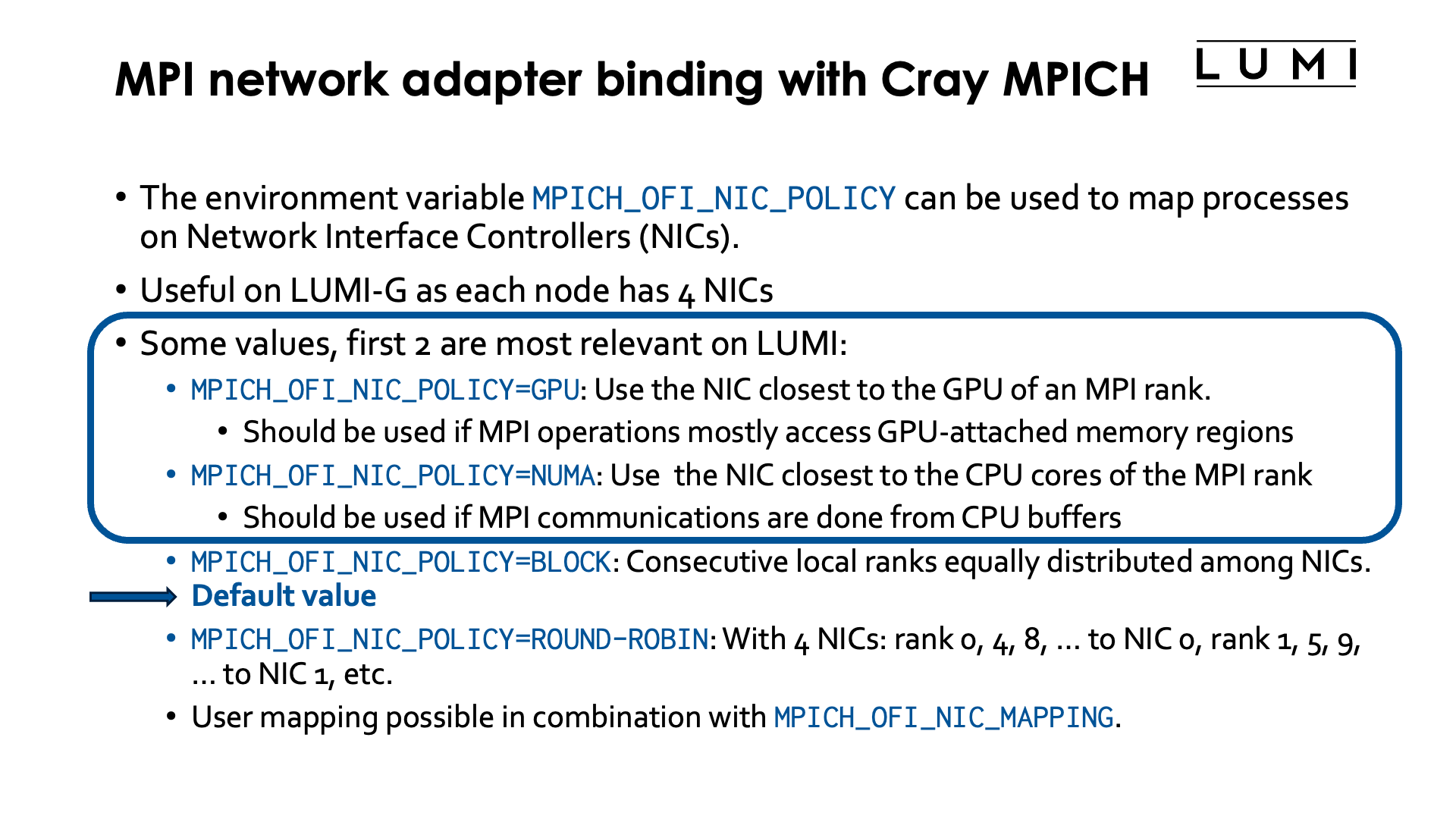
Binding network interface controllers (NICs) to MPI ranks can help to improve inter-node communication on nodes with more than one NIC for the high-speed interconnect. On LUMI, this is the case for the GPU nodes, but there are also many Cray systems out in the world with multiple NICs in CPU nodes, usually one per socket.
On LUMI, this matters only on LUMI-G, and in fact, the default binding is usually not optimal so it is useful to change the default NIC binding.
This is done through the environment variable MPICH_OFI_NIC_POLICY.
We did already briefly discuss this environment variable when discussing
GPU-aware MPI in the
HPE Cray Programming Environment chapter.
Several values are possible, but the first two are the most relevant ones for LUMI:
-
MPICH_OFI_NIC_POLICY=GPU: Cray MPICH will try to use the NIC that is closest to the GPU used by the MPI rank. This is the most useful value if most MPI communications are done directly from or to GPU-attached memory regions. Obviously this only makes sense if GPU-aware MPI is enabled throughMPICH_GPU_SUPPORT_ENABLED=1. -
MPICH_OFI_NIC_POLICY=NUMA: Cray MPICH will try to use the NIC that is closest to the NUMA domain of the CPU cores assigned to an MPI rank. This value is useful if most MPI operations are done to or from buffers in CPU-attached memory.Note that if an optimal mapping between GCDs and CCDs is done (discussed later in this chapter), both values are equivalent. However, on shared nodes where a proper mapping between CPU cores and GCDs is not possible, selecting the right value for a particular code may help a lot to improve performance.
-
MPICH_OFI_NIC_POLICY=BLOCK: Consecutive local ranks are equally distributed among NICs. E.g., with 8 ranks and 4 NICs, rank 0 an 1 would use NIC 0, rank 1 and 2 NIC 1, etc.This is the default value but on the LUMI-G nodes often not the proper one.
-
MPICH_OFI_NIC_POLICY=ROUND-ROBIN: With 4 NICs: rank 0 goes to NIC 0, rank 1 to NIC 1, rank 2 to NIC 2, rank 3 to NIC 3, rank 4 again to NIC 0, etc. So basically rank i goes to NIC i mod #NICs. -
User defined mappings are also possible by combining
MPICH_OFI_NIC_POLICY=USERwith defining a mapping throughMPICH_OFI_NIC_MAPPING.
More information on these environment variables can be found in the intro_mpi man page on the system or
the intro_mpi page in the online CPE documentation.
Refining core binding in OpenMP applications

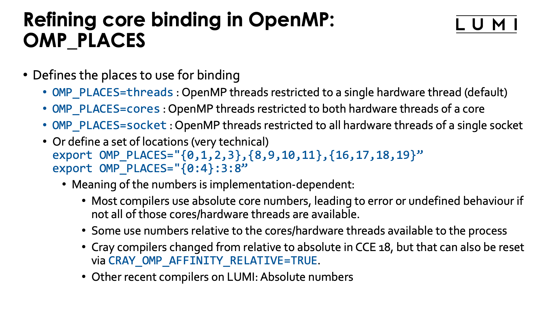

In a Slurm batch job step, threads of a shared memory process will be contained to all
hardware threads of all available cores on the first node of your allocation. To contain
a shared memory program to the hardware threads asked for in the allocation (i.e., to ensure
that --hint=[no]multithread has effect) you'd have to start the shared memory program with
srun in a regular job step.
Any multithreaded executable run as a shared memory job or ranks in a hybrid MPI/multithread job,
will - when started properly via srun - get access to a group of cores via an affinity mask.
In some cases you will want to manually refine the way individual threads of each process are
mapped onto the available hardware threads.
In OpenMP, this is usually done through environment variables (it can also be done partially in the program through library calls). A number of environment variables is standardised in the OpenMP standard, but some implementations offer some additional non-standard ones, or non-standard values for the standard environment variables. Below we discuss the more important of the standard ones:
-
OMP_NUM_THREADSis used to set the number of CPU threads OpenMP will use. In its most basic form this is a single number (but you can give multiple comma-separated numbers for nested parallelism).OpenMP programs on LUMI will usually correctly detect how many hardware threads are available to the task and use one OpenMP thread per hardware thread. There are cases where you may want to ask for a certain number of hardware threads when allocating resources, e.g., to easily get a good mapping of tasks on cores, but do not want to use them all, e.g., because your application is too memory bandwidth or cache constrained and using fewer threads actually gives better overall performance on a per-node basis.
-
OMP_PLACESis used to restrict each OpenMP thread to a group of hardware threads. Possible values include:OMP_PLACES=threadsto restrict OpenMP threads to a single hardware threadOMP_PLACES=coresto restrict each OpenMP threads to a single core (but all hardware threads associated with that core)OMP_PLACES=socketsto restrict each OpenMP thread to the hardware threads of a single socket-
And it is possible to give a list with explicit values, e.g.,
export OMP_PLACES="{0:4}:3:8"which is also equivalent to
export OMP_PLACES="{0,1,2,3},{8,9,10,11},{16,17,18,19}"so each OpenMP thread is restricted to a different group of 4 hardware threads. The numbers in the list are not the physical Linux hardware thread numbers, but are relative to the hardware threads available in the affinity mask of the task.
More general,
{a:b}:c:dmeans b numbers starting from a (so a, a+1, ..., a+b-1), repeated c times, at every repeat shifted by d. There are more variants to generate lists of places and we show another one in the example below. But in all the syntax may look strange and there are manuals that give the wrong information (including some versions of the manual for the GNU OpenMP runtime).The main issue is that the meaning of those numbers is not set in the OpenMP standard, but is implementation-dependent. Most implementations use the absolute virtual core (hardware thread) numbers as used by the operating system and in the Slurm bind masks, and the behaviour is undefined or an error occurs if those virtual cores are not available to the process. In some implementations, core numbers are relative within the cores assigned to the process. The latter has the advantage that it always works as long as enough cores are available to the task while the former can only be used on exclusive nodes as otherwise you don't know in advance what physical cores will be available to you. But as on a non-exclusive node you cannot know what the layout of your tasks will be, using such accurate placing doesn't make sense anyway as it is really meant to be able to exploit the cache and memory hierarchy of a node.
On LUMI, all recent compilers use absolute core numbers. But before CCE 18, the Cray compilers used relative numbering and from CCE 18 on you can still get that behaviour by setting the environment variable
CRAY_OMP_AFFINITY_RELATIVEtoTRUE.Unfortunately, not all compiler manuals are clear about this and some experimenting may be needed.
Note that this is different from the core numbers that would be used in
--cpu-bind=map_cpuor--gpu-bind=mask_cpuwhich sets the CPUs or groups of CPUs available to each process and which always use the physical numbering and not a numbering that is local to the job allocation. Moreover, Slurm can only assign cores to processes (tasks in a job step) and not to individual threads in a process. The latter is precisely where OpenMP environment variables come in if OpenMP is used to create and manage the threads. -
Some OpenMP implementations also support other abstract names for
OMP_PLACESto align with last-level caches or NUMA domains.
-
OMP_PROC_BIND: Sets how threads are distributed over the places. Possible values are:-
OMP_PROC_BIND=false: Turn off OpenMP thread binding. Each thread will get access to all hardware threads available in to the task (and defined by a Linux affinity mask in Slurm). -
OMP_PROC_BIND=close: If more places are available than there are OpenMP threads, then try to put the OpenMP threads in different places as close as possible to the master thread. In general, bind as close as possible to the master thread while still distributing for load balancing. -
OMP_PROC_BIND=spread: Spread threads out as evenly as possible over the places available to the task. -
OMP_PROC_BIND=master: Bind threads to the same place as the master thread. The place is determined by theOMP_PLACESenvironment variable and it is clear this makes no sense if that place is just a single hardware thread or single core as all threads would then be competing for the resources of a single core.
Multiple values of
close,spreadandmasterin a comma-separated list are possible to organise nested OpenMP parallelism, but this is outside of the scope of this tutorial.The Cray Compilation Environment also has an additional non-standard option
auto, which is actually the default and tries to do a reasonable job for most cases. On the other compilers on LUMI, the default behaviour isfalseunless the next environment variable,OMP_PLACES, is specified. -
-
OMP_DISPLAY_AFFINITY: When set totTRUEinformation about the affinity binding of each thread will be shown which is good for debugging purposes.
For single-level OpenMP parallelism, the omp_check and hybrid_check programs from the lumi-CPEtools modules
can also be used to check the OpenMP thread binding.
Some examples (click to expand)
Consider the following job script:
#!/bin/bash
#SBATCH --account=project_46YXXXXXX
#SBATCH --job-name=omp-demo-1
#SBATCH --output %x-%j.txt
#SBATCH --partition=standard
#SBATCH --nodes=1
#SBATCH --hint=multithread
#SBATCH --time=5:00

module load LUMI/25.03 partition/C lumi-CPEtools/1.2-cpeCray-25.03-hpcat-0.9

set -x
export OMP_NUM_THREADS=4
export OMP_PROC_BIND=false
srun -n 1 -c 32 --hint=multithread   omp_check -r
srun -n 1 -c 16 --hint=nomultithread omp_check -r

export OMP_NUM_THREADS=4
unset OMP_PROC_BIND
srun -n 1 -c 32 --hint=multithread   omp_check -r
srun -n 1 -c 16 --hint=nomultithread omp_check -r

export OMP_NUM_THREADS=4
export OMP_PROC_BIND=close
srun -n 1 -c 32 --hint=multithread   omp_check -r
srun -n 1 -c 16 --hint=nomultithread omp_check -r

export OMP_NUM_THREADS=4
export OMP_PROC_BIND=spread
srun -n 1 -c 32 --hint=multithread   omp_check -r
srun -n 1 -c 16 --hint=nomultithread omp_check -r

export OMP_NUM_THREADS=4
export OMP_PROC_BIND=close
export OMP_PLACES=threads
srun -n 1 -c 32 --hint=multithread   omp_check -r
export OMP_PLACES=cores
srun -n 1 -c 32 --hint=multithread   omp_check -r

export OMP_NUM_THREADS=4
export OMP_PROC_BIND=close
export OMP_PLACES="{0:8}:4:8"
srun -n 1 -c 32 --hint=multithread   omp_check -r

export OMP_NUM_THREADS=4
export OMP_PROC_BIND=close
export OMP_PLACES="{0:8}:4:8"
export CRAY_OMP_AFFINITY_RELATIVE=TRUE
srun -n 1 -c 32 --hint=multithread   omp_check -r

export OMP_NUM_THREADS=4
export OMP_PROC_BIND=close
export OMP_PLACES="{0:4,16:4}:4:4"
unset CRAY_OMP_AFFINITY_RELATIVE
srun -n 1 -c 32 --hint=multithread   omp_check -r

export OMP_NUM_THREADS=4
export OMP_PROC_BIND=close
export OMP_PLACES="{0:4,128:4}:4:4"
unset CRAY_OMP_AFFINITY_RELATIVE
srun -n 1 -c 32 --hint=multithread   omp_check -r
set +x
Let's check the output step by step:
In the first block we run 2 srun commands that actually both use 16 cores, but first with
hardware threading enabled in Slurm and then with multithread mode off in Slurm:
+ export OMP_NUM_THREADS=4
+ OMP_NUM_THREADS=4
+ export OMP_PROC_BIND=false
+ OMP_PROC_BIND=false
+ srun -n 1 -c 32 --hint=multithread omp_check -r

Running 4 threads in a single process

++ omp_check: OpenMP thread   0/4   on cpu   0/256 of nid001077 mask 0-15, 128-143
++ omp_check: OpenMP thread   1/4   on cpu 137/256 of nid001077 mask 0-15, 128-143
++ omp_check: OpenMP thread   2/4   on cpu 129/256 of nid001077 mask 0-15, 128-143
++ omp_check: OpenMP thread   3/4   on cpu 143/256 of nid001077 mask 0-15, 128-143

+ srun -n 1 -c 16 --hint=nomultithread omp_check -r

Running 4 threads in a single process

++ omp_check: OpenMP thread   0/4   on cpu   0/256 of nid001077 mask 0-15
++ omp_check: OpenMP thread   1/4   on cpu  15/256 of nid001077 mask 0-15
++ omp_check: OpenMP thread   2/4   on cpu   1/256 of nid001077 mask 0-15
++ omp_check: OpenMP thread   3/4   on cpu  14/256 of nid001077 mask 0-15
OMP_PROC_BIND was explicitly set to false to disable the Cray Compilation Environment default behaviour.
The masks reported by omp_check cover all hardware threads available to the task in Slurm: Both hardware
threads for the 16 first cores in the multithread case and just the primary hardware thread on the first 16 cores
in the second case. So each OpenMP thread can in principle migrate over all available hardware threads.
In the second block we unset the PROC_BIND environment variable to demonstrate the behaviour of the
Cray Compilation Environment. The output would be different had we used the cpeGNU or cpeAOCC version.
+ export OMP_NUM_THREADS=4
+ OMP_NUM_THREADS=4
+ unset OMP_PROC_BIND
+ srun -n 1 -c 32 --hint=multithread omp_check -r

Running 4 threads in a single process

++ omp_check: OpenMP thread   0/4   on cpu   1/256 of nid001077 mask 0-3, 128-131
++ omp_check: OpenMP thread   1/4   on cpu   4/256 of nid001077 mask 4-7, 132-135
++ omp_check: OpenMP thread   2/4   on cpu   8/256 of nid001077 mask 8-11, 136-139
++ omp_check: OpenMP thread   3/4   on cpu 142/256 of nid001077 mask 12-15, 140-143

+ srun -n 1 -c 16 --hint=nomultithread omp_check -r

Running 4 threads in a single process

++ omp_check: OpenMP thread   0/4   on cpu   0/256 of nid001077 mask 0-3
++ omp_check: OpenMP thread   1/4   on cpu   4/256 of nid001077 mask 4-7
++ omp_check: OpenMP thread   2/4   on cpu   9/256 of nid001077 mask 8-11
++ omp_check: OpenMP thread   3/4   on cpu  15/256 of nid001077 mask 12-15
The default behaviour of the CCE is very nice: Threads are nicely spread out over the available cores and then all get access to their own group of hardware threads that in this case with 4 threads for 16 cores spans 4 cores for each thread. In fact, also in other cases the default behaviour of CCE will be a binding that works well for many cases.
In the next experiment we demonstrate the close binding:
+ export OMP_NUM_THREADS=4
+ OMP_NUM_THREADS=4
+ export OMP_PROC_BIND=close
+ OMP_PROC_BIND=close
+ srun -n 1 -c 32 --hint=multithread omp_check -r

Running 4 threads in a single process

++ omp_check: OpenMP thread   0/4   on cpu   0/256 of nid001077 mask 0
++ omp_check: OpenMP thread   1/4   on cpu 128/256 of nid001077 mask 128
++ omp_check: OpenMP thread   2/4   on cpu   1/256 of nid001077 mask 1
++ omp_check: OpenMP thread   3/4   on cpu 129/256 of nid001077 mask 129

+ srun -n 1 -c 16 --hint=nomultithread omp_check -r

Running 4 threads in a single process

++ omp_check: OpenMP thread   0/4   on cpu   0/256 of nid001077 mask 0
++ omp_check: OpenMP thread   1/4   on cpu   1/256 of nid001077 mask 1
++ omp_check: OpenMP thread   2/4   on cpu   2/256 of nid001077 mask 2
++ omp_check: OpenMP thread   3/4   on cpu   3/256 of nid001077 mask 3
In the first case, with Slurm multithreading mode on, we see that the 4 threads are now concentrated on only 2 cores but each gets pinned to its own hardware thread. In general this behaviour is not what one wants if more cores are available as on each core two threads will now be competing for available resources. In the second case, with Slurm multithreading disabled, the threads are bound to the first 4 cores, with one core for each thread.
Next we demonstrate the spread binding:
+ export OMP_NUM_THREADS=4
+ OMP_NUM_THREADS=4
+ export OMP_PROC_BIND=spread
+ OMP_PROC_BIND=spread
+ srun -n 1 -c 32 --hint=multithread omp_check -r

Running 4 threads in a single process

++ omp_check: OpenMP thread   0/4   on cpu   0/256 of nid001077 mask 0
++ omp_check: OpenMP thread   1/4   on cpu   4/256 of nid001077 mask 4
++ omp_check: OpenMP thread   2/4   on cpu   8/256 of nid001077 mask 8
++ omp_check: OpenMP thread   3/4   on cpu  12/256 of nid001077 mask 12

+ srun -n 1 -c 16 --hint=nomultithread omp_check -r

Running 4 threads in a single process

++ omp_check: OpenMP thread   0/4   on cpu   0/256 of nid001077 mask 0
++ omp_check: OpenMP thread   1/4   on cpu   4/256 of nid001077 mask 4
++ omp_check: OpenMP thread   2/4   on cpu   8/256 of nid001077 mask 8
++ omp_check: OpenMP thread   3/4   on cpu  12/256 of nid001077 mask 12
The result is now the same in both cases as we have fewer threads than physical cores. Each OpenMP thread is bound to a single core, but these cores are spread out over the first 16 cores of the node.
Next we return to the close binding but try both threads and cores as places
with Slurm multithreading turned on for both cases:
+ export OMP_NUM_THREADS=4
+ OMP_NUM_THREADS=4
+ export OMP_PROC_BIND=close
+ OMP_PROC_BIND=close
+ export OMP_PLACES=threads
+ OMP_PLACES=threads
+ srun -n 1 -c 32 --hint=multithread omp_check -r

Running 4 threads in a single process

++ omp_check: OpenMP thread   0/4   on cpu   0/256 of nid001077 mask 0
++ omp_check: OpenMP thread   1/4   on cpu 128/256 of nid001077 mask 128
++ omp_check: OpenMP thread   2/4   on cpu   1/256 of nid001077 mask 1
++ omp_check: OpenMP thread   3/4   on cpu 129/256 of nid001077 mask 129

+ export OMP_PLACES=cores
+ OMP_PLACES=cores
+ srun -n 1 -c 32 --hint=multithread omp_check -r

Running 4 threads in a single process

++ omp_check: OpenMP thread   0/4   on cpu   0/256 of nid001077 mask 0, 128
++ omp_check: OpenMP thread   1/4   on cpu   1/256 of nid001077 mask 1, 129
++ omp_check: OpenMP thread   2/4   on cpu 130/256 of nid001077 mask 2, 130
++ omp_check: OpenMP thread   3/4   on cpu   3/256 of nid001077 mask 3, 131
With threads as places we get again the distribution with two OpenMP threads on each
physical core, each with their own hardware thread. With cores as places, we get only one
thread per physical core, but each thread has access to both hardware threads of that physical core.
And lastly we play a bit with custom placements:
+ export OMP_NUM_THREADS=4
+ OMP_NUM_THREADS=4
+ export OMP_PROC_BIND=close
+ OMP_PROC_BIND=close
+ export 'OMP_PLACES={0:8}:4:8'
+ OMP_PLACES='{0:8}:4:8'
+ srun -n 1 -c 32 --hint=multithread omp_check -r
[CCE OMP: host=nid001002 pid=180671 tid=180671 id=0] ignoring out-of-bounds CPU 16
[CCE OMP: host=nid001002 pid=180671 tid=180671 id=0] ignoring out-of-bounds CPU 17
[CCE OMP: host=nid001002 pid=180671 tid=180671 id=0] ignoring out-of-bounds CPU 18
[CCE OMP: host=nid001002 pid=180671 tid=180671 id=0] ignoring out-of-bounds CPU 19
[CCE OMP: host=nid001002 pid=180671 tid=180671 id=0] ignoring out-of-bounds CPU 20
[CCE OMP: host=nid001002 pid=180671 tid=180671 id=0] ignoring out-of-bounds CPU 21
[CCE OMP: host=nid001002 pid=180671 tid=180671 id=0] ignoring out-of-bounds CPU 22
[CCE OMP: host=nid001002 pid=180671 tid=180671 id=0] ignoring out-of-bounds CPU 23
[CCE OMP: host=nid001002 pid=180671 tid=180671 id=0] ignoring empty place 2
[CCE OMP: host=nid001002 pid=180671 tid=180671 id=0] ignoring out-of-bounds CPU 24
[CCE OMP: host=nid001002 pid=180671 tid=180671 id=0] ignoring out-of-bounds CPU 25
[CCE OMP: host=nid001002 pid=180671 tid=180671 id=0] ignoring out-of-bounds CPU 26
[CCE OMP: host=nid001002 pid=180671 tid=180671 id=0] ignoring out-of-bounds CPU 27
[CCE OMP: host=nid001002 pid=180671 tid=180671 id=0] ignoring out-of-bounds CPU 28
[CCE OMP: host=nid001002 pid=180671 tid=180671 id=0] ignoring out-of-bounds CPU 29
[CCE OMP: host=nid001002 pid=180671 tid=180671 id=0] ignoring out-of-bounds CPU 30
[CCE OMP: host=nid001002 pid=180671 tid=180671 id=0] ignoring out-of-bounds CPU 31
[CCE OMP: host=nid001002 pid=180671 tid=180671 id=0] ignoring empty place 3

Running 4 threads in a single process

++ omp_check: host nid001002 OpenMP thread   0/4   cpu   0/256 mask (0-7)
++ omp_check: host nid001002 OpenMP thread   1/4   cpu   8/256 mask (8-15)
++ omp_check: host nid001002 OpenMP thread   2/4   cpu   4/256 mask (0-7)
++ omp_check: host nid001002 OpenMP thread   3/4   cpu   9/256 mask (8-15)
This example does not run without issues. Let us explain why.
OMP_PLACES='{0:8}:4:8 means: Take starting from core with logical number 0 8 cores and
repeat this 4 times, shifting by 8 each time, so effectively
OMP_PLACES="{ 0,1,2,3,4,5,6,7},{8,9,10,11,12,13,14,15},{16,17,18,19,20,21,22,23},{24,25,26,27,27,28,30,31}"
This would work if OMP_PLACES where relative numbers as we do have 32 hardware threads in our allocation.
However, as we used --hint-multithread we got hardware thread 0 till 15 and 128 till 143,
so the two last places are invalid as cores 16 till 31 are not assigned to the task. So only the
first two places are used, with thread 0 landing in the first place, theread 1 in the
second, thread 2 again in the first and thread 3 in the last.
This is clearly shown by omp_check which shows us the OS numbering for hardware threads.
This can be repaired by setting CRAY_OMP_AFFINITY_RELATIVE=TRUE:
+ export OMP_NUM_THREADS=4
+ OMP_NUM_THREADS=4
+ export OMP_PROC_BIND=close
+ OMP_PROC_BIND=close
+ export 'OMP_PLACES={0:8}:4:8'
+ OMP_PLACES='{0:8}:4:8'
+ export CRAY_OMP_AFFINITY_RELATIVE=TRUE
+ CRAY_OMP_AFFINITY_RELATIVE=TRUE
+ srun -n 1 -c 32 --hint=multithread omp_check -r

Running 4 threads in a single process

++ omp_check: host nid001002 OpenMP thread   0/4   cpu   0/256 mask (0-7)
++ omp_check: host nid001002 OpenMP thread   1/4   cpu   8/256 mask (8-15)
++ omp_check: host nid001002 OpenMP thread   2/4   cpu 128/256 mask (128-135)
++ omp_check: host nid001002 OpenMP thread   3/4   cpu 136/256 mask (136-143)
Let's try another variant with
OMP_PACES={0:4,16:4}:4:4
which is equivalent to
OMP_PLACES={0,1,2,3,16,17,18,19},{4,5,6,7,20,21,22,23},{8,9,10,11,24,25,26,27},{12,13,14,15,28,29,30,31}"
With CRAY_OMP_AFFINITY_RELATIVE unset we now get
+ export OMP_NUM_THREADS=4
+ OMP_NUM_THREADS=4
+ export OMP_PROC_BIND=close
+ OMP_PROC_BIND=close
+ export 'OMP_PLACES={0:4,16:4}:4:4'
+ OMP_PLACES='{0:4,16:4}:4:4'
+ unset CRAY_OMP_AFFINITY_RELATIVE
+ srun -n 1 -c 32 --hint=multithread omp_check -r
[CCE OMP: host=nid001002 pid=180708 tid=180708 id=0] ignoring out-of-bounds CPU 16
[CCE OMP: host=nid001002 pid=180708 tid=180708 id=0] ignoring out-of-bounds CPU 17
[CCE OMP: host=nid001002 pid=180708 tid=180708 id=0] ignoring out-of-bounds CPU 18
[CCE OMP: host=nid001002 pid=180708 tid=180708 id=0] ignoring out-of-bounds CPU 19
[CCE OMP: host=nid001002 pid=180708 tid=180708 id=0] ignoring out-of-bounds CPU 20
[CCE OMP: host=nid001002 pid=180708 tid=180708 id=0] ignoring out-of-bounds CPU 21
[CCE OMP: host=nid001002 pid=180708 tid=180708 id=0] ignoring out-of-bounds CPU 22
[CCE OMP: host=nid001002 pid=180708 tid=180708 id=0] ignoring out-of-bounds CPU 23
[CCE OMP: host=nid001002 pid=180708 tid=180708 id=0] ignoring out-of-bounds CPU 24
[CCE OMP: host=nid001002 pid=180708 tid=180708 id=0] ignoring out-of-bounds CPU 25
[CCE OMP: host=nid001002 pid=180708 tid=180708 id=0] ignoring out-of-bounds CPU 26
[CCE OMP: host=nid001002 pid=180708 tid=180708 id=0] ignoring out-of-bounds CPU 27
[CCE OMP: host=nid001002 pid=180708 tid=180708 id=0] ignoring out-of-bounds CPU 28
[CCE OMP: host=nid001002 pid=180708 tid=180708 id=0] ignoring out-of-bounds CPU 29
[CCE OMP: host=nid001002 pid=180708 tid=180708 id=0] ignoring out-of-bounds CPU 30
[CCE OMP: host=nid001002 pid=180708 tid=180708 id=0] ignoring out-of-bounds CPU 31

Running 4 threads in a single process

++ omp_check: host nid001002 OpenMP thread   0/4   cpu   0/256 mask (0-3)
++ omp_check: host nid001002 OpenMP thread   1/4   cpu   5/256 mask (4-7)
++ omp_check: host nid001002 OpenMP thread   2/4   cpu   8/256 mask (8-11)
++ omp_check: host nid001002 OpenMP thread   3/4   cpu  12/256 mask (12-15)
Things go wrong again because of the absolute numbering and we see that only the first four
hardware threads of each place is being used. This can again be corrected by setting
CRAY_OMP_AFFINITY_RELATIVE=TRUE, or by simply correcting the list of cores for
OMP_PLACES as we know what cores will be assigned to the job step. Using
{0:4,128:4}:4:4, we get
+ export OMP_NUM_THREADS=4
+ OMP_NUM_THREADS=4
+ export OMP_PROC_BIND=close
+ OMP_PROC_BIND=close
+ export 'OMP_PLACES={0:4,128:4}:4:4'
+ OMP_PLACES='{0:4,128:4}:4:4'
+ unset CRAY_OMP_AFFINITY_RELATIVE
+ srun -n 1 -c 32 --hint=multithread omp_check -r

Running 4 threads in a single process

++ omp_check: host nid001002 OpenMP thread   0/4   cpu   0/256 mask (0-3, 128-131)
++ omp_check: host nid001002 OpenMP thread   1/4   cpu 132/256 mask (4-7, 132-135)
++ omp_check: host nid001002 OpenMP thread   2/4   cpu   8/256 mask (8-11, 136-139)
++ omp_check: host nid001002 OpenMP thread   3/4   cpu 140/256 mask (12-15, 140-143)
Absolute or relative OMP_PLACES? (Click to expand)
The last part of the previous example also gives us a clue how we can easily check if
an OpenMP implementation uses absolute or relative numbering for the cores in OMP_PLACES.
Consider the following test program:
#!/bin/bash
#SBATCH --account=project_46YXXXXXX
#SBATCH --job-name=omp-demo-2
#SBATCH --output %x-%j.txt
#SBATCH --partition=standard
#SBATCH --nodes=1
#SBATCH --hint=multithread
#SBATCH --time=5:00

module load LUMI/25.03 partition/C lumi-CPEtools/1.2-cpeCray-25.03-hpcat-0.9

module load lumi-CPEtools/1.2-cpeGNU-25.03-hpcat-0.9
echo -e "\n\nTesting cpeGNU...\n"
set -x
export OMP_NUM_THREADS=4
export OMP_PROC_BIND=close
export OMP_PLACES="{0:4,16:4}:4:4"
srun -n 1 -c 32 --hint=multithread omp_check -r

export OMP_PLACES="{0:4,128:4}:4:4"
srun -n 1 -c 32 --hint=multithread omp_check -r
set +x

module load lumi-CPEtools/1.2-cpeCray-25.03-hpcat-0.9
echo -e "\n\nTesting cpeCray...\n"
set -x
export OMP_NUM_THREADS=4
export OMP_PROC_BIND=close
export OMP_PLACES="{0:4,16:4}:4:4"
srun -n 1 -c 32 --hint=multithread   omp_check -r

export OMP_PLACES="{0:4,128:4}:4:4"
srun -n 1 -c 32 --hint=multithread omp_check -r
set +x

module load lumi-CPEtools/1.2-cpeAOCC-25.03-hpcat-0.9
echo -e "\n\nTesting cpeAOCC...\n"
set -x
export OMP_NUM_THREADS=4
export OMP_PROC_BIND=close
export OMP_PLACES="{0:4,16:4}:4:4"
srun -n 1 -c 32 --hint=multithread   omp_check -r

export OMP_PLACES="{0:4,128:4}:4:4"
srun -n 1 -c 32 --hint=multithread omp_check -r
set +x

module load partition/G lumi-CPEtools/1.2-cpeAMD-25.03-hpcat-0.9
echo -e "\n\nTesting cpeAMD...\n"
set -x
export OMP_NUM_THREADS=4
export OMP_PROC_BIND=close
export OMP_PLACES="{0:4,16:4}:4:4"
srun -n 1 -c 32 --hint=multithread   omp_check -r

export OMP_PLACES="{0:4,128:4}:4:4"
srun -n 1 -c 32 --hint=multithread omp_check -r
set +x

module load lumi-CPEtools/1.2-cpeCray-25.03-hpcat-0.9
echo -e "\n\nTesting cpeCray with CRAY_OMP_AFFINITY_RELATIVE=TRUE...\n"
set -x
export OMP_NUM_THREADS=4
export OMP_PROC_BIND=close
export OMP_PLACES="{0:4,16:4}:4:4"
export CRAY_OMP_AFFINITY_RELATIVE=TRUE
srun -n 1 -c 32 --hint=multithread   omp_check -r

export OMP_PLACES="{0:4,128:4}:4:4"
srun -n 1 -c 32 --hint=multithread omp_check -r
set +x
For the GNU compilers, we get
Testing cpeGNU...

+ export OMP_NUM_THREADS=4
+ OMP_NUM_THREADS=4
+ export OMP_PROC_BIND=close
+ OMP_PROC_BIND=close
+ export 'OMP_PLACES={0:4,16:4}:4:4'
+ OMP_PLACES='{0:4,16:4}:4:4'
+ srun -n 1 -c 32 --hint=multithread omp_check -r

Running 4 threads in a single process

++ omp_check: host nid001202 OpenMP thread   0/4   cpu   0/256 mask (0-3)
++ omp_check: host nid001202 OpenMP thread   1/4   cpu   4/256 mask (4-7)
++ omp_check: host nid001202 OpenMP thread   2/4   cpu   8/256 mask (8-11)
++ omp_check: host nid001202 OpenMP thread   3/4   cpu  12/256 mask (12-15)

+ export 'OMP_PLACES={0:4,128:4}:4:4'
+ OMP_PLACES='{0:4,128:4}:4:4'
+ srun -n 1 -c 32 --hint=multithread omp_check -r

Running 4 threads in a single process

++ omp_check: host nid001202 OpenMP thread   0/4   cpu   0/256 mask (0-3, 128-131)
++ omp_check: host nid001202 OpenMP thread   1/4   cpu   4/256 mask (4-7, 132-135)
++ omp_check: host nid001202 OpenMP thread   2/4   cpu   8/256 mask (8-11, 136-139)
++ omp_check: host nid001202 OpenMP thread   3/4   cpu  12/256 mask (12-15, 140-143)
We get no warning, but from the CPU masks reported by omp_check we can clearly see
that absolute numbering is used: In the first case, we don't get to see the second
hardware thread of each virtual core as the virtual cores numbered 16 till 31 are simply
discarded without warning as they are not available to the job.
For the Cray compilers in LUMI/25.03 we get:
Testing cpeCray...

+ export OMP_NUM_THREADS=4
+ OMP_NUM_THREADS=4
+ export OMP_PROC_BIND=close
+ OMP_PROC_BIND=close
+ export 'OMP_PLACES={0:4,16:4}:4:4'
+ OMP_PLACES='{0:4,16:4}:4:4'
+ srun -n 1 -c 32 --hint=multithread omp_check -r
[CCE OMP: host=nid001202 pid=62647 tid=62647 id=0] ignoring out-of-bounds CPU 16
[CCE OMP: host=nid001202 pid=62647 tid=62647 id=0] ignoring out-of-bounds CPU 17
[CCE OMP: host=nid001202 pid=62647 tid=62647 id=0] ignoring out-of-bounds CPU 18
[CCE OMP: host=nid001202 pid=62647 tid=62647 id=0] ignoring out-of-bounds CPU 19
[CCE OMP: host=nid001202 pid=62647 tid=62647 id=0] ignoring out-of-bounds CPU 20
[CCE OMP: host=nid001202 pid=62647 tid=62647 id=0] ignoring out-of-bounds CPU 21
[CCE OMP: host=nid001202 pid=62647 tid=62647 id=0] ignoring out-of-bounds CPU 22
[CCE OMP: host=nid001202 pid=62647 tid=62647 id=0] ignoring out-of-bounds CPU 23
[CCE OMP: host=nid001202 pid=62647 tid=62647 id=0] ignoring out-of-bounds CPU 24
[CCE OMP: host=nid001202 pid=62647 tid=62647 id=0] ignoring out-of-bounds CPU 25
[CCE OMP: host=nid001202 pid=62647 tid=62647 id=0] ignoring out-of-bounds CPU 26
[CCE OMP: host=nid001202 pid=62647 tid=62647 id=0] ignoring out-of-bounds CPU 27
[CCE OMP: host=nid001202 pid=62647 tid=62647 id=0] ignoring out-of-bounds CPU 28
[CCE OMP: host=nid001202 pid=62647 tid=62647 id=0] ignoring out-of-bounds CPU 29
[CCE OMP: host=nid001202 pid=62647 tid=62647 id=0] ignoring out-of-bounds CPU 30
[CCE OMP: host=nid001202 pid=62647 tid=62647 id=0] ignoring out-of-bounds CPU 31

Running 4 threads in a single process

++ omp_check: host nid001202 OpenMP thread   0/4   cpu   0/256 mask (0-3)
++ omp_check: host nid001202 OpenMP thread   1/4   cpu   4/256 mask (4-7)
++ omp_check: host nid001202 OpenMP thread   2/4   cpu   8/256 mask (8-11)
++ omp_check: host nid001202 OpenMP thread   3/4   cpu  12/256 mask (12-15)

+ export 'OMP_PLACES={0:4,128:4}:4:4'
+ OMP_PLACES='{0:4,128:4}:4:4'
+ srun -n 1 -c 32 --hint=multithread omp_check -r

Running 4 threads in a single process

++ omp_check: host nid001202 OpenMP thread   0/4   cpu   0/256 mask (0-3, 128-131)
++ omp_check: host nid001202 OpenMP thread   1/4   cpu 132/256 mask (4-7, 132-135)
++ omp_check: host nid001202 OpenMP thread   2/4   cpu 136/256 mask (8-11, 136-139)
++ omp_check: host nid001202 OpenMP thread   3/4   cpu 140/256 mask (12-15, 140-143)
Here we get a clear warning that the core numbers 16 till 31 are invalid in the first case, which shows that absolute numbers are used. The second case then confirms this as it works well using the absolute core numbers available to the job step.
For the AOCC compiler in LUMI/25.03 we get:
Testing cpeAOCC...

+ export OMP_NUM_THREADS=4
+ OMP_NUM_THREADS=4
+ export OMP_PROC_BIND=close
+ OMP_PROC_BIND=close
+ export 'OMP_PLACES={0:4,16:4}:4:4'
+ OMP_PLACES='{0:4,16:4}:4:4'
+ srun -n 1 -c 32 --hint=multithread omp_check -r
OMP: Warning #124: Ignoring invalid OS proc ID 16.

Running 4 threads in a single process

++ omp_check: host nid001202 OpenMP thread   0/4   cpu   1/256 mask (0-3)
++ omp_check: host nid001202 OpenMP thread   1/4   cpu   4/256 mask (4-7)
++ omp_check: host nid001202 OpenMP thread   2/4   cpu   8/256 mask (8-11)
++ omp_check: host nid001202 OpenMP thread   3/4   cpu  12/256 mask (12-15)

+ export 'OMP_PLACES={0:4,128:4}:4:4'
+ OMP_PLACES='{0:4,128:4}:4:4'
+ srun -n 1 -c 32 --hint=multithread omp_check -r

Running 4 threads in a single process

++ omp_check: host nid001202 OpenMP thread   0/4   cpu   1/256 mask (0-3, 128-131)
++ omp_check: host nid001202 OpenMP thread   1/4   cpu 132/256 mask (4-7, 132-135)
++ omp_check: host nid001202 OpenMP thread   2/4   cpu 136/256 mask (8-11, 136-139)
++ omp_check: host nid001202 OpenMP thread   3/4   cpu 143/256 mask (12-15, 140-143)
For the first srun, we do see a warning now that processor ID 16 is invalid. It does
not bombard us with warnings about the other cores, but again we clearly see that
absolute numbers are used.
And we see the same thing for cpeAMD:
+ OMP_NUM_THREADS=4
+ export OMP_PROC_BIND=close
+ OMP_PROC_BIND=close
+ export 'OMP_PLACES={0:4,16:4}:4:4'
+ OMP_PLACES='{0:4,16:4}:4:4'
+ srun -n 1 -c 32 --hint=multithread omp_check -r
OMP: Warning #124: Ignoring invalid OS proc ID 16.

Running 4 threads in a single process

++ omp_check: host nid001202 OpenMP thread   0/4   cpu   1/256 mask (0-3)
++ omp_check: host nid001202 OpenMP thread   1/4   cpu   4/256 mask (4-7)
++ omp_check: host nid001202 OpenMP thread   2/4   cpu  10/256 mask (8-11)
++ omp_check: host nid001202 OpenMP thread   3/4   cpu  12/256 mask (12-15)

+ export 'OMP_PLACES={0:4,128:4}:4:4'
+ OMP_PLACES='{0:4,128:4}:4:4'
+ srun -n 1 -c 32 --hint=multithread omp_check -r

Running 4 threads in a single process

++ omp_check: host nid001202 OpenMP thread   0/4   cpu   1/256 mask (0-3, 128-131)
++ omp_check: host nid001202 OpenMP thread   1/4   cpu   5/256 mask (4-7, 132-135)
++ omp_check: host nid001202 OpenMP thread   2/4   cpu 136/256 mask (8-11, 136-139)
++ omp_check: host nid001202 OpenMP thread   3/4   cpu 143/256 mask (12-15, 140-143)
Finally, to show what happens with an OpenMP runtime that uses relative numbering,
consider the Cray compilers with CRAY_OMP_AFFINITY_RELATIVE=TRUE:
Testing cpeCray with CRAY_OMP_AFFINITY_RELATIVE=TRUE...

+ export OMP_NUM_THREADS=4
+ OMP_NUM_THREADS=4
+ export OMP_PROC_BIND=close
+ OMP_PROC_BIND=close
+ export 'OMP_PLACES={0:4,16:4}:4:4'
+ OMP_PLACES='{0:4,16:4}:4:4'
+ export CRAY_OMP_AFFINITY_RELATIVE=TRUE
+ CRAY_OMP_AFFINITY_RELATIVE=TRUE
+ srun -n 1 -c 32 --hint=multithread omp_check -r

Running 4 threads in a single process

++ omp_check: host nid001202 OpenMP thread   0/4   cpu   0/256 mask (0-3, 128-131)
++ omp_check: host nid001202 OpenMP thread   1/4   cpu 132/256 mask (4-7, 132-135)
++ omp_check: host nid001202 OpenMP thread   2/4   cpu 136/256 mask (8-11, 136-139)
++ omp_check: host nid001202 OpenMP thread   3/4   cpu 140/256 mask (12-15, 140-143)

+ export 'OMP_PLACES={0:4,128:4}:4:4'
+ OMP_PLACES='{0:4,128:4}:4:4'
+ srun -n 1 -c 32 --hint=multithread omp_check -r
[CCE OMP: host=nid001202 pid=65132 tid=65132 id=0] ignoring out-of-bounds CPU 128
[CCE OMP: host=nid001202 pid=65132 tid=65132 id=0] ignoring out-of-bounds CPU 129
[CCE OMP: host=nid001202 pid=65132 tid=65132 id=0] ignoring out-of-bounds CPU 130
[CCE OMP: host=nid001202 pid=65132 tid=65132 id=0] ignoring out-of-bounds CPU 131
[CCE OMP: host=nid001202 pid=65132 tid=65132 id=0] ignoring out-of-bounds CPU 132
[CCE OMP: host=nid001202 pid=65132 tid=65132 id=0] ignoring out-of-bounds CPU 133
[CCE OMP: host=nid001202 pid=65132 tid=65132 id=0] ignoring out-of-bounds CPU 134
[CCE OMP: host=nid001202 pid=65132 tid=65132 id=0] ignoring out-of-bounds CPU 135
[CCE OMP: host=nid001202 pid=65132 tid=65132 id=0] ignoring out-of-bounds CPU 136
[CCE OMP: host=nid001202 pid=65132 tid=65132 id=0] ignoring out-of-bounds CPU 137
[CCE OMP: host=nid001202 pid=65132 tid=65132 id=0] ignoring out-of-bounds CPU 138
[CCE OMP: host=nid001202 pid=65132 tid=65132 id=0] ignoring out-of-bounds CPU 139
[CCE OMP: host=nid001202 pid=65132 tid=65132 id=0] ignoring out-of-bounds CPU 140
[CCE OMP: host=nid001202 pid=65132 tid=65132 id=0] ignoring out-of-bounds CPU 141
[CCE OMP: host=nid001202 pid=65132 tid=65132 id=0] ignoring out-of-bounds CPU 142
[CCE OMP: host=nid001202 pid=65132 tid=65132 id=0] ignoring out-of-bounds CPU 143

Running 4 threads in a single process

++ omp_check: host nid001202 OpenMP thread   0/4   cpu   0/256 mask (0-3)
++ omp_check: host nid001202 OpenMP thread   1/4   cpu   5/256 mask (4-7)
++ omp_check: host nid001202 OpenMP thread   2/4   cpu   8/256 mask (8-11)
++ omp_check: host nid001202 OpenMP thread   3/4   cpu  12/256 mask (12-15)
Now the first case runs fine, giving 8 hardware threads on 4 physical cores for each of the tasks, but the second case now causes issues as there are only 32 hardware threads in the allocation, so the numbers 128 till 143 don't make sense.
We only discussed a subset of the environment variables defined in the OpenMP standard. Several implementations
also offer additional environment variables, e.g.,
a number of GOMP_* environment variables in the GNU Compiler Collection implementation or KMP_* variables in the Intel compiler (not available on LUMI).
Some further documentation:
-
The
OMP_*environment variables and a number of environment variables specific for the runtime libraries of the Cray Compiling Environment are discussed in theintro_openmpmanual page, section "Environment variables". -
A list of OMP_ environment variables in the OpenMP 5.1 standard (as the current list in the HTML version of the 5.2 standard has some problems).
GPU binding with ROCR_VISIBLE_DEVICES

The ROCR_VISIBLE_DEVICES environment variable restricts access to GPUs at the ROCm platform runtime
level. Contrary to control groups however this mechanism is compatible with the Peer2Peer IPC used by
GPU-aware Cray MPI for intra-node communication.
The value of the ROCR_VISIBLE_DEVICES environment variable is a list of device indices that will be
exposed to the applications. The device indices do depend on the control group. Visible devices in a control
group are always numbered from 0.
So though ROCR_VISIBLE_DEVICES has the same function as affinity masks for CPUs, it is different in
many respects.
-
Affinity masks are part of the Linux kernel and fully OS-controlled, while
ROCR_VISIBLE_DEVICESis interpreted in the ROCm™ stack. -
Affinity masks are set through an OS call and that call can enforce that the new mask cannot be less restrictive than the parent mask.
ROCR_VISIBLE_DEVICESis just an environment variable, so at the time that you try to set it to a value that you shouldn't use, there is no check. -
Affinity masks always use the global numbering of hardware threads while
ROCR_VISIBLE_DEVICESuses the local numbering in the currently active control group. So the GPU that corresponds to 0 inROCR_VISIBLE_DEVICESis not always the same GPU.
Alternative values for ROCR_VISIBLE_DEVICES (click to expand)
Instead of device indices, ROCR_VISIBLE_DEVICES also accepts GPU UUIDs that are unique to each
GPU. This is less practical then it seems as the UUIDs of GPUs are different on each node so one
would need to discover them first before they can be used.
Combining Slurm task binding with ROCR_VISIBLE_DEVICES
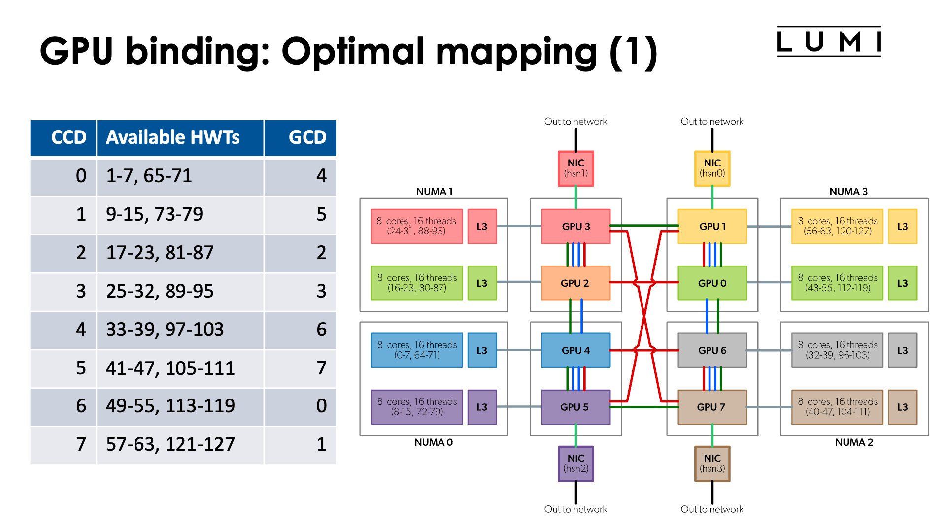
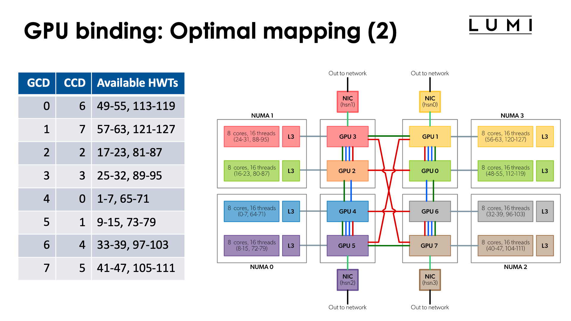
In the chapter on the architecture of LUMI we discussed what a LUMI-G really looks like.
The full topology of a LUMI-G compute node is shown in the figure:

Note that the numbering of GCDs does not correspond to the numbering of CCDs/cores. However, for optimal memory transfers (and certainly if cache-coherent memory access from CPU to GPU would be used) it is better to ensure that each GCD collaborates with the matched CCD in an MPI rank. So we have the mapping:
| CCD | HWTs | Available HWTs | CPU mask (without HWTs) | GCD |
|---|---|---|---|---|
| 0 | 0-7, 64-71 | 1-7, 65-71 | 0xfe | 4 |
| 1 | 8-15, 72-79 | 9-15, 73-79 | 0xfe00 | 5 |
| 2 | 16-23, 80-87 | 17-23, 81-87 | 0xfe0000 | 2 |
| 3 | 24-32, 88-95 | 25-32, 89-95 | 0xfe000000 | 3 |
| 4 | 32-39, 96-103 | 33-39, 97-103 | 0xfe00000000 | 6 |
| 5 | 40-47, 104-111 | 41-47, 105-111 | 0xfe0000000000 | 7 |
| 6 | 48-55, 112-119 | 49-55, 113-119 | 0xfe000000000000 | 0 |
| 7 | 56-63, 120-127 | 57-63, 121-127 | 0xfe00000000000000 | 1 |
or the reverse mapping
| GCD | CCD | HWTs | Available HWTs | CPU mask (without HWTs) |
|---|---|---|---|---|
| 0 | 6 | 48-55, 112-119 | 49-55, 113-119 | 0xfe000000000000 |
| 1 | 7 | 56-63, 120-127 | 57-63, 121-127 | 0xfe00000000000000 |
| 2 | 2 | 16-23, 80-87 | 17-23, 81-87 | 0xfe0000 |
| 3 | 3 | 24-32, 88-95 | 25-32, 89-95 | 0xfe000000 |
| 4 | 0 | 0-7, 64-71 | 1-7, 65-71 | 0xfe |
| 5 | 1 | 8-15, 72-79 | 9-15, 73-79 | 0xfe00 |
| 6 | 4 | 32-39, 96-103 | 33-39, 97-103 | 0xfe00000000 |
| 7 | 5 | 40-47, 104-111 | 41-47, 105-111 | 0xfe0000000000 |

Moreover, if you look more carefully at the topology, you can see that the connections between the GCDs contain a number of rings:
-
Green ring: 0 - 1 - 3 - 2 - 4 - 5 - 7 - 6 - 0
-
Red ring: 0 - 1 - 5 - 4 - 6 - 7 - 3 - 2 - 0
-
Sharing some connections with the previous ones, but can be combined with the green ring: 0 - 1 - 5 - 4 - 2 - 3 - 7 - 6 - 0
So if your application would use a ring mapping for communication and use communication from GPU buffers for that, than it may be advantageous to map the MPI ranks on one of those rings which would mean that neither the order of the CCDs nor the order of the GCDs is trivial.
Some other topologies can also be mapped on these connections (but unfortunately not a 3D cube).
Note: The red ring and green ring correspond to the red and green rings on page 6 of the "Introducing AMD CDNATM 2 Architecture" whitepaper.
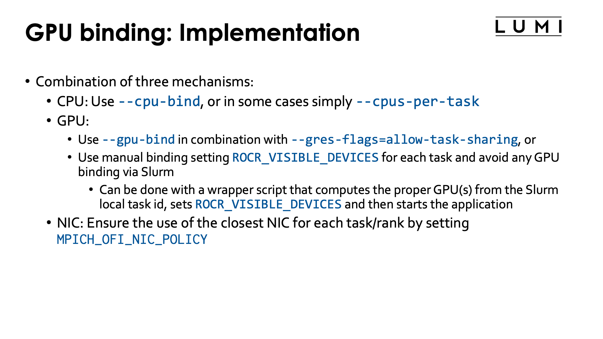
To implement a proper CCD-to-GCD mapping we will use three mechanisms:
-
On the CPU side we'll use Slurm
--cpu-bind. Sometimes we can also simply use-cor--cpus-per-task(in particular in the case below with linear ordering of the CCDs and 7 cores per task) -
On the GPU side we have a choice between two mechanism:
-
Since the January 2026 system update, it is possible to use
--gpu-bindto define a custom mapping (but automatic withclosestdoesn't seem to work reliably) on the condition that--gres-flags=allow-task-sharingis also used as otherwise some essential interprocess communication mechanisms for RCCL and MPI will not work properly. -
The technique that has been used since the start of LUMI can of course still be used. We can manually assign GPUs via a different value of
ROCR_VISIBLE_DEVICESfor each thread. To accomplish this we will have to write a wrapper script which we will generate in the job script, or you could use some clever bash as the command started bysrun.
-
-
On the NIC side, one can then ensure that the proper NIC will be used by each MPI rank by setting
MPICH_OFI_NIC_POLICYto eitherGPUorNUMA. Which one does not matter as when the proper mappings are used, the CPU cores and GCD used by an MPI rank are in the same NUMA node.
Let us start with the simplest case:
Linear assignment of GCD, then match the cores
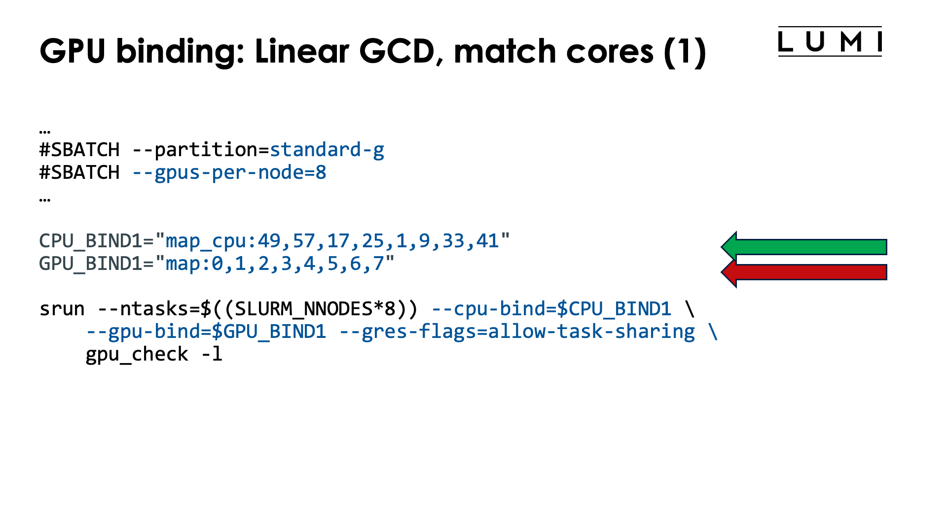
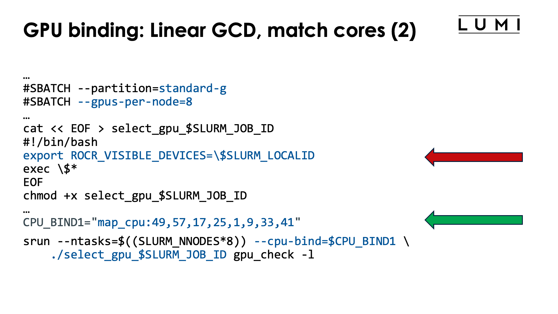
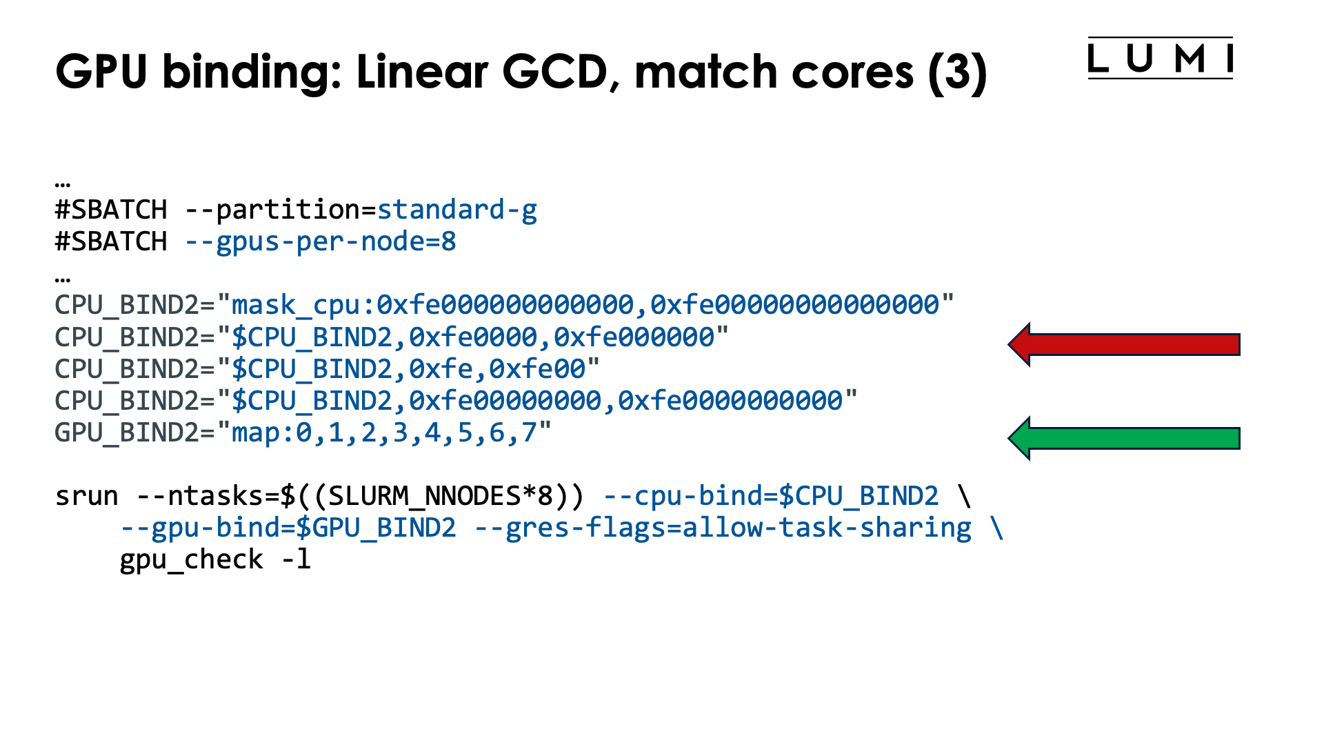
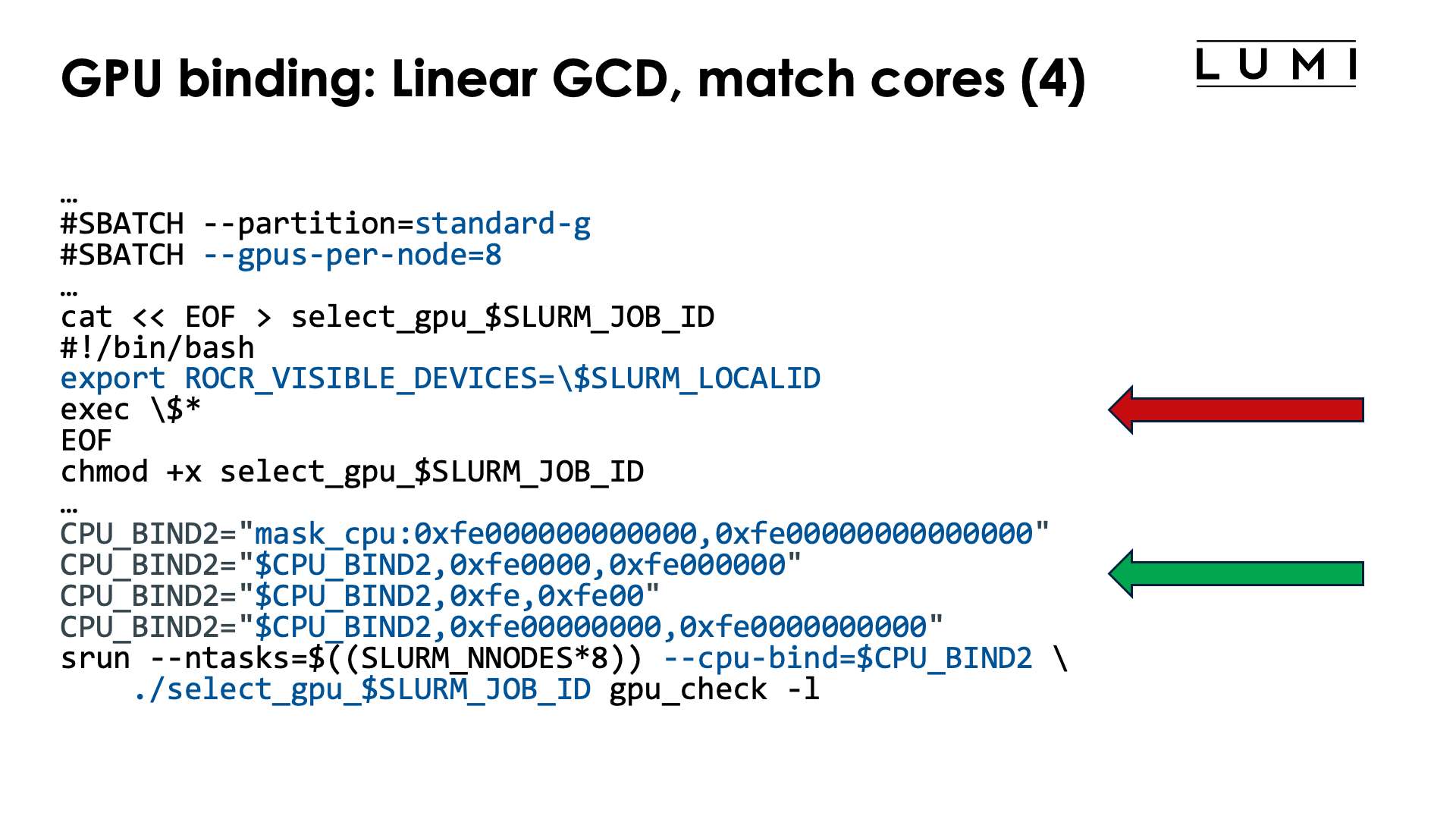
In this scenario, task 0 uses GCD 0 and the matching CCD, CCD 6, task 1 uses GCD 1 and the matching CCD 7, etc. So the following table is the relevant one to use:
| GCD | CCD | HWTs | Available HWTs | CPU mask (without HWTs) |
|---|---|---|---|---|
| 0 | 6 | 48-55, 112-119 | 49-55, 113-119 | 0xfe000000000000 |
| 1 | 7 | 56-63, 120-127 | 57-63, 121-127 | 0xfe00000000000000 |
| 2 | 2 | 16-23, 80-87 | 17-23, 81-87 | 0xfe0000 |
| 3 | 3 | 24-32, 88-95 | 25-32, 89-95 | 0xfe000000 |
| 4 | 0 | 0-7, 64-71 | 1-7, 65-71 | 0xfe |
| 5 | 1 | 8-15, 72-79 | 9-15, 73-79 | 0xfe00 |
| 6 | 4 | 32-39, 96-103 | 33-39, 97-103 | 0xfe00000000 |
| 7 | 5 | 40-47, 104-111 | 41-47, 105-111 | 0xfe0000000000 |
Mapping each task to a GCD is easy in this case, as the Slurm task with local task ID $SLURM_LOCALID is mapped on GCD $SLURM_LOCALID. However, the CPU mapping is more complex, but to build the CPU mask or list, we simply have to read the 4th or 5th column from the above table from the first to the last line.
One possible job script to implement this order is:
#!/bin/bash
#SBATCH --account=project_46YXXXXXX
#SBATCH --job-name=map-linear-GCD
#SBATCH --output %x-%j.txt
#SBATCH --partition=standard-g
#SBATCH --gpus-per-node=8
#SBATCH --nodes=2
#SBATCH --time=5:00

module load LUMI/25.03 partition/G lumi-CPEtools/1.2-cpeCray-25.03-hpcat-0.9

# Mapping:
# | Task | GCD | CCD | HWTs           | Available HWTs | CPU mask (w/o HWTs) |
# |-----:|----:|----:|:---------------|:---------------|--------------------:|
# |    0 |   0 |   6 | 48-55, 112-119 | 49-55, 113-119 |   0xfe000000000000  |
# |    1 |   1 |   7 | 56-63, 120-127 | 57-63, 121-127 | 0xfe00000000000000  |
# |    2 |   2 |   2 | 16-23, 80-87   | 17-23, 81-87   |           0xfe0000  |
# |    3 |   3 |   3 | 24-32, 88-95   | 25-32, 89-95   |         0xfe000000  |
# |    4 |   4 |   0 | 0-7, 64-71     | 1-7, 65-71     |               0xfe  |
# |    5 |   5 |   1 | 8-15, 72-79    | 9-15, 73-79    |             0xfe00  |
# |    6 |   6 |   4 | 32-39, 96-103  | 33-39, 97-103  |       0xfe00000000  |
# |    7 |   7 |   5 | 40-47, 104-111 | 41-47, 105-111 |     0xfe0000000000  |

# Mapping from column 2 (GCD)
GPU_BIND="map:0,1,2,3,4,5,6,7"

# Mapping from column 5 (Available HWTs)
CPU_BIND1="map_cpu:49,57,17,25,1,9,33,41"

# Mapping from column 6 (CPU mask)
CPU_BIND2="mask_cpu:0xfe000000000000,0xfe00000000000000"
CPU_BIND2="$CPU_BIND2,0xfe0000,0xfe000000"
CPU_BIND2="$CPU_BIND2,0xfe,0xfe00"
CPU_BIND2="$CPU_BIND2,0xfe00000000,0xfe0000000000"

export MPICH_GPU_SUPPORT_ENABLED=1
export MPICH_OFI_NIC_POLICY=GPU

echo -e "\nPure MPI:\n"
srun --ntasks=$((SLURM_NNODES*8)) --cpu-bind=$CPU_BIND1 \
    --gpu-bind=$GPU_BIND --gres-flags=allow-task-sharing \
    mpi_check -r
srun --ntasks=$((SLURM_NNODES*8)) --cpu-bind=$CPU_BIND1 \
    --gpu-bind=$GPU_BIND --gres-flags=allow-task-sharing \
    gpu_check -l

echo -e "\nHybrid:\n"
srun --ntasks=$((SLURM_NNODES*8)) --cpu-bind=$CPU_BIND2 \
    --gpu-bind=$GPU_BIND --gres-flags=allow-task-sharing \
    hybrid_check -r
srun --ntasks=$((SLURM_NNODES*8)) --cpu-bind=$CPU_BIND2 \
    --gpu-bind=$GPU_BIND --gres-flags=allow-task-sharing \
    gpu_check -l
To select the GPUs we either use a map with numbers of cores (ideal for pure MPI programs)
or masks (the only option for hybrid programs). The mask that we give in the example uses
7 cores per CCD and always skips the first core, as is required on LUMI as
the first core of each chiplet
is reserved and not available to Slurm jobs.
We could avoid selecting the GPUs in this case as this we use the default
order of assigning GPUs for --gpus-per-task=1, but it is just safer and
not much work to also specify the GPU order, which is trivial here and
is done with --gpu-bind="map:0,1,2,3,4,5,6,7".
Instead of the somewhat complicated --ntasks with srun we could have specified --ntasks-per-node=8
on a #SBATCH line which would have fixed the structure for all srun commands. Even though we want
to use all GPUs in the node, --gpus-per-node or an equivalent option has to be specified either
as an #SBATCH line or with each srun command or no GPUs will be made available to the tasks
started by the srun command.
Note the output of the second srun command:
MPI 000 - OMP 000 - HWT 049 (CCD6) - Node nid005143 - RT_GPU_ID 0 - GPU_ID 0 - Bus_ID c1(GCD0/CCD6)
MPI 001 - OMP 000 - HWT 057 (CCD7) - Node nid005143 - RT_GPU_ID 0 - GPU_ID 1 - Bus_ID c6(GCD1/CCD7)
MPI 002 - OMP 000 - HWT 017 (CCD2) - Node nid005143 - RT_GPU_ID 0 - GPU_ID 2 - Bus_ID c9(GCD2/CCD2)
MPI 003 - OMP 000 - HWT 025 (CCD3) - Node nid005143 - RT_GPU_ID 0 - GPU_ID 3 - Bus_ID ce(GCD3/CCD3)
MPI 004 - OMP 000 - HWT 001 (CCD0) - Node nid005143 - RT_GPU_ID 0 - GPU_ID 4 - Bus_ID d1(GCD4/CCD0)
MPI 005 - OMP 000 - HWT 009 (CCD1) - Node nid005143 - RT_GPU_ID 0 - GPU_ID 5 - Bus_ID d6(GCD5/CCD1)
MPI 006 - OMP 000 - HWT 033 (CCD4) - Node nid005143 - RT_GPU_ID 0 - GPU_ID 6 - Bus_ID d9(GCD6/CCD4)
MPI 007 - OMP 000 - HWT 041 (CCD5) - Node nid005143 - RT_GPU_ID 0 - GPU_ID 7 - Bus_ID de(GCD7/CCD5)
...
With the -l option of gpu_check, we also print some information about the CCD that a core belongs to and the
GCD and corresponding optimal CCD for each PCIe bus ID, which makes it very easy to check if the
mapping is as intended. Note that the GCDs are indeed in the linear order starting with GCD0.
Alternative with ROCR_VISIBLE_DEVICES and a wrapper script (click to expand)
A possible job script is now:
#!/bin/bash
#SBATCH --account=project_46YXXXXXX
#SBATCH --job-name=map-linear-GCD-wrapper
#SBATCH --output %x-%j.txt
#SBATCH --partition=standard-g
#SBATCH --gpus-per-node=8
#SBATCH --nodes=2
#SBATCH --time=5:00

module load LUMI/25.03 partition/G lumi-CPEtools/1.2-cpeCray-25.03-hpcat-0.9

# Mapping:
# | Task | GCD | CCD | HWTs           | Available HWTs | CPU mask (w/o HWTs) |
# |-----:|----:|----:|:---------------|:---------------|--------------------:|
# |    0 |   0 |   6 | 48-55, 112-119 | 49-55, 113-119 |   0xfe000000000000  |
# |    1 |   1 |   7 | 56-63, 120-127 | 57-63, 121-127 | 0xfe00000000000000  |
# |    2 |   2 |   2 | 16-23, 80-87   | 17-23, 81-87   |           0xfe0000  |
# |    3 |   3 |   3 | 24-32, 88-95   | 25-32, 89-95   |         0xfe000000  |
# |    4 |   4 |   0 | 0-7, 64-71     | 1-7, 65-71     |               0xfe  |
# |    5 |   5 |   1 | 8-15, 72-79    | 9-15, 73-79    |             0xfe00  |
# |    6 |   6 |   4 | 32-39, 96-103  | 33-39, 97-103  |       0xfe00000000  |
# |    7 |   7 |   5 | 40-47, 104-111 | 41-47, 105-111 |     0xfe0000000000  |

# Mapping from column 2 (GCD)
cat << EOF > select_gpu_$SLURM_JOB_ID
#!/bin/bash
export ROCR_VISIBLE_DEVICES=\$SLURM_LOCALID
exec \$*
EOF
chmod +x select_gpu_$SLURM_JOB_ID

# Mapping from column 5 (Available HWTs)
CPU_BIND1="map_cpu:49,57,17,25,1,9,33,41"

# Mapping from column 6 (CPU mask)
CPU_BIND2="mask_cpu:0xfe000000000000,0xfe00000000000000"
CPU_BIND2="$CPU_BIND2,0xfe0000,0xfe000000"
CPU_BIND2="$CPU_BIND2,0xfe,0xfe00"
CPU_BIND2="$CPU_BIND2,0xfe00000000,0xfe0000000000"

export MPICH_GPU_SUPPORT_ENABLED=1
export MPICH_OFI_NIC_POLICY=GPU

echo -e "\nPure MPI:\n"
srun --ntasks=$((SLURM_NNODES*8)) --cpu-bind=$CPU_BIND1 ./select_gpu_$SLURM_JOB_ID mpi_check -r
srun --ntasks=$((SLURM_NNODES*8)) --cpu-bind=$CPU_BIND1 ./select_gpu_$SLURM_JOB_ID gpu_check -l

echo -e "\nHybrid:\n"
srun --ntasks=$((SLURM_NNODES*8)) --cpu-bind=$CPU_BIND2 ./select_gpu_$SLURM_JOB_ID hybrid_check -r
srun --ntasks=$((SLURM_NNODES*8)) --cpu-bind=$CPU_BIND2 ./select_gpu_$SLURM_JOB_ID gpu_check -l

/bin/rm -f select_gpu_$SLURM_JOB_ID
To select the GPUs we either use a map with numbers of cores (ideal for pure MPI programs)
or masks (the only option for hybrid programs). The mask that we give in the example uses
7 cores per CCD and always skips the first core, as is required on LUMI as
the first core of each chiplet
is reserved and not available to Slurm jobs. To select the right GPU for ROCR_VISIBLE_DEVICES
we can use the Slurm local task ID which is
also what the MPI rank will be.
We use a so-called "bash here document"
to generate the script. Note that in the bash here document
we needed to protect the $ with a backslash (so use \$) as otherwise the variables would
already be expanded when generating the script file.
Linear assignment of the CCDs, then match the GCD
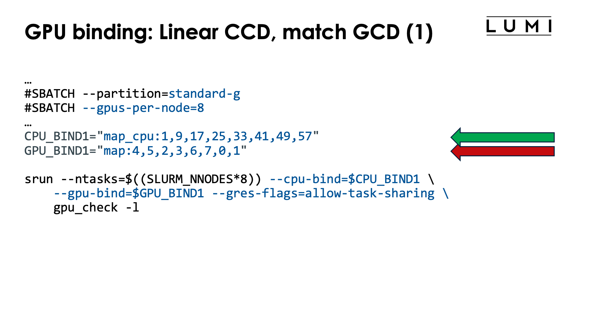
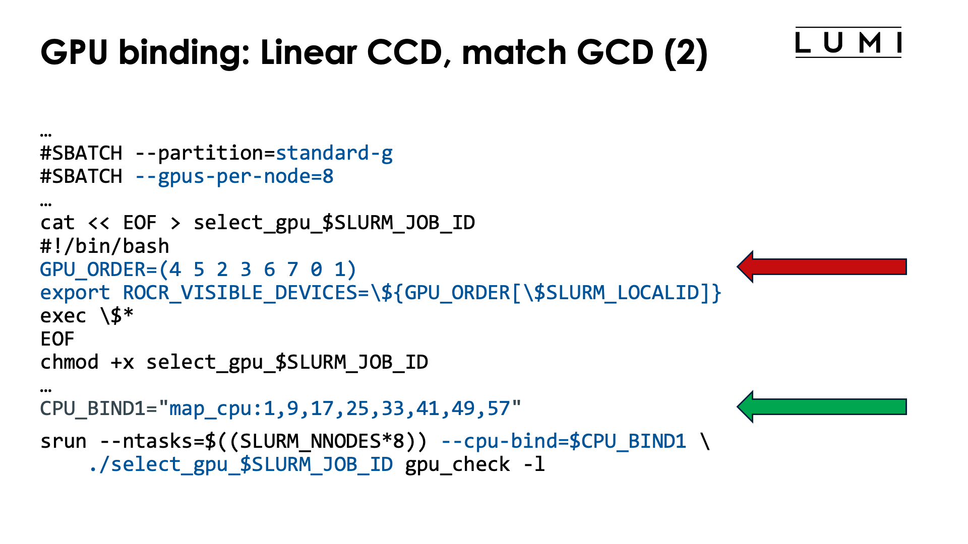
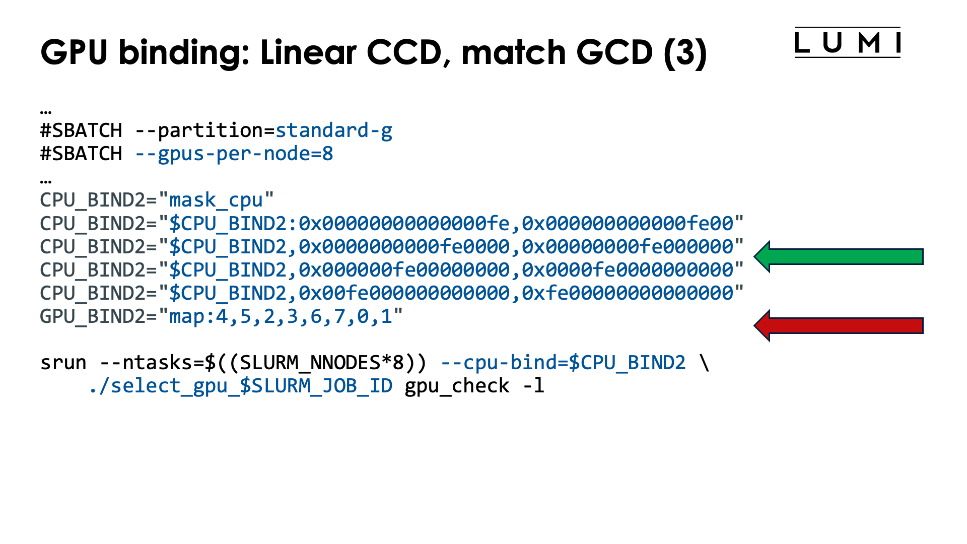
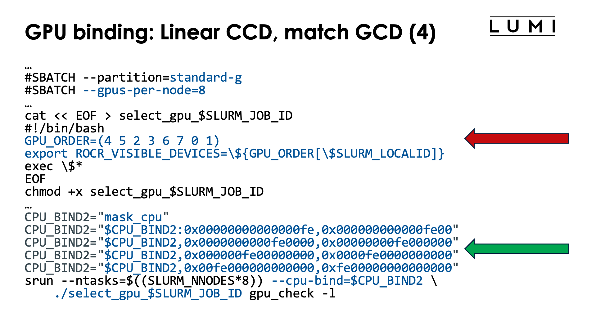
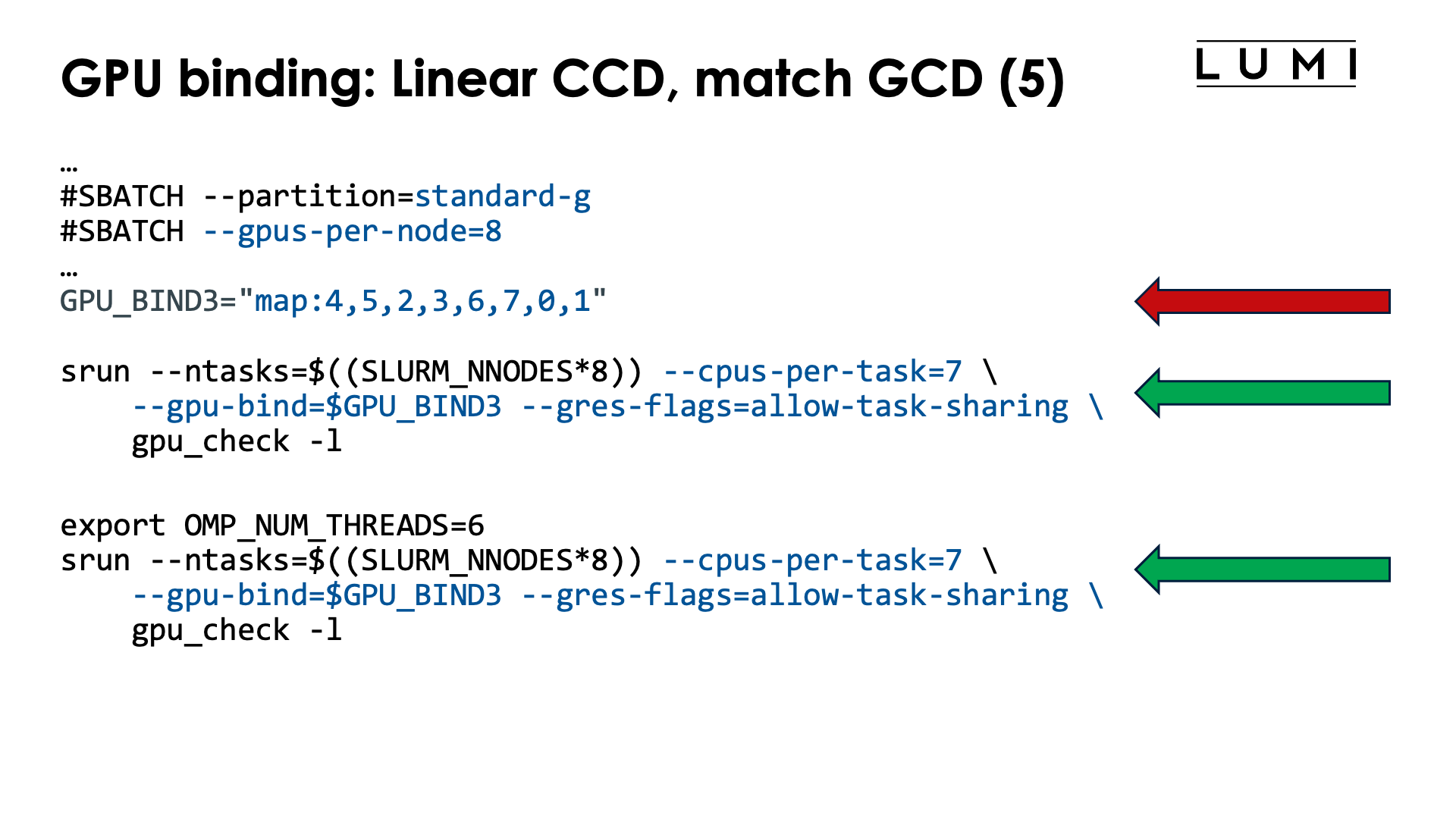
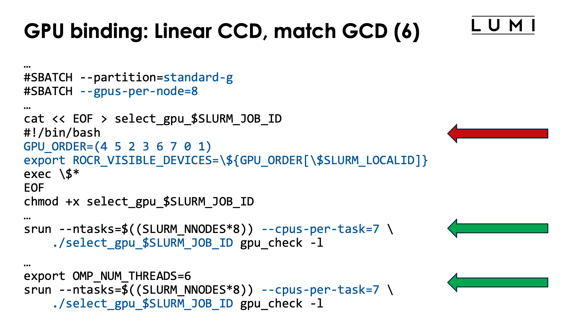
Modifying the order of the GPUs to match the CCDs which are assigned as CCD i for local task i, is a bit more complicated as we still need to ensure that each task lands on a different CCD while assigning the GPU is more difficult. The relevant table for this example is:
| CCD | HWTs | Available HWTs | CPU mask (without HWTs) | GCD |
|---|---|---|---|---|
| 0 | 0-7, 64-71 | 1-7, 65-71 | 0xfe | 4 |
| 1 | 8-15, 72-79 | 9-15, 73-79 | 0xfe00 | 5 |
| 2 | 16-23, 80-87 | 17-23, 81-87 | 0xfe0000 | 2 |
| 3 | 24-32, 88-95 | 25-32, 89-95 | 0xfe000000 | 3 |
| 4 | 32-39, 96-103 | 33-39, 97-103 | 0xfe00000000 | 6 |
| 5 | 40-47, 104-111 | 41-47, 105-111 | 0xfe0000000000 | 7 |
| 6 | 48-55, 112-119 | 49-55, 113-119 | 0xfe000000000000 | 0 |
| 7 | 56-63, 120-127 | 57-63, 121-127 | 0xfe00000000000000 | 1 |
To modify the order of the GPUs, we now use an array with the desired order in the select_gpu script,
and that order can be read from the last column in the above table.
With the current setup of LUMI, with one core reserved on each chiplet, there are now two options
to get the proper CPUs:
-
We can use masks to define the cores for each slot, but they will now look more regular, or
-
we can simply use
--cpus-per-task=7and then further restrict the number of threads per task withOMP_NUM_THREADS.
The job script (for option 1) now becomes:
#!/bin/bash
#SBATCH --account=project_46YXXXXXX
#SBATCH --job-name=map-linear-CCD
#SBATCH --output %x-%j.txt
#SBATCH --partition=standard-g
#SBATCH --gpus-per-node=8
#SBATCH --nodes=2
#SBATCH --time=5:00

module load LUMI/25.03 partition/G lumi-CPEtools/1.2-cpeCray-25.03-hpcat-0.9

# Mapping:
# | Task | CCD | HWTs           | Available HWTs | CPU mask (w/o HWTs) | GCD |
# |-----:|----:|:---------------|:---------------|--------------------:|----:|
# |    0 |   0 | 0-7, 64-71     | 1-7, 65-71     |               0xfe  |   4 |
# |    1 |   1 | 8-15, 72-79    | 9-15, 73-79    |             0xfe00  |   5 |
# |    2 |   2 | 16-23, 80-87   | 17-23, 81-87   |           0xfe0000  |   2 |
# |    3 |   3 | 24-32, 88-95   | 25-32, 89-95   |         0xfe000000  |   3 |
# |    4 |   4 | 32-39, 96-103  | 33-39, 97-103  |       0xfe00000000  |   6 |
# |    5 |   5 | 40-47, 104-111 | 41-47, 105-111 |     0xfe0000000000  |   7 |
# |    6 |   6 | 48-55, 112-119 | 49-55, 113-119 |   0xfe000000000000  |   0 |
# |    7 |   7 | 56-63, 120-127 | 57-63, 121-127 | 0xfe00000000000000  |   1 |

# Mapping from column 6 (GCD)
GPU_BIND="map:4,5,2,3,6,7,0,1"

# Mapping from column 4 (Available HWTs)
CPU_BIND1="map_cpu:1,9,17,25,33,41,49,57"

# Mapping from column 5 (CPU masks)
CPU_BIND2="mask_cpu"
CPU_BIND2="$CPU_BIND2:0x00000000000000fe,0x000000000000fe00"
CPU_BIND2="$CPU_BIND2,0x0000000000fe0000,0x00000000fe000000"
CPU_BIND2="$CPU_BIND2,0x000000fe00000000,0x0000fe0000000000"
CPU_BIND2="$CPU_BIND2,0x00fe000000000000,0xfe00000000000000"

export MPICH_GPU_SUPPORT_ENABLED=1
export MPICH_OFI_NIC_POLICY=GPU

echo -e "\nPure MPI:\n"
srun --ntasks=$((SLURM_NNODES*8)) --cpu-bind=$CPU_BIND1 \
    --gpu-bind=$GPU_BIND --gres-flags=allow-task-sharing \
    mpi_check -r
srun --ntasks=$((SLURM_NNODES*8)) --cpu-bind=$CPU_BIND1 \
    --gpu-bind=$GPU_BIND --gres-flags=allow-task-sharing \
    gpu_check -l

echo -e "\nPure MPI with --cpus-per-task:\n"
srun --ntasks=$((SLURM_NNODES*8)) --cpus-per-task=7 \
    --gpu-bind=$GPU_BIND --gres-flags=allow-task-sharing \
    mpi_check -r
OMP_NUM_THREADS=1 srun --ntasks=$((SLURM_NNODES*8)) --cpus-per-task=7 \
    --gpu-bind=$GPU_BIND --gres-flags=allow-task-sharing \
    gpu_check -l

echo -e "\nHybrid:\n"
srun --ntasks=$((SLURM_NNODES*8)) --cpu-bind=$CPU_BIND2 \
    --gpu-bind=$GPU_BIND --gres-flags=allow-task-sharing \
    hybrid_check -r
srun --ntasks=$((SLURM_NNODES*8)) --cpu-bind=$CPU_BIND2 \
    --gpu-bind=$GPU_BIND --gres-flags=allow-task-sharing \
    gpu_check -l

echo -e "\nHybrid with --cpus-per-task:\n"
srun --ntasks=$((SLURM_NNODES*8)) --cpus-per-task=7 \
    --gpu-bind=$GPU_BIND --gres-flags=allow-task-sharing \
    hybrid_check -r
srun --ntasks=$((SLURM_NNODES*8)) --cpus-per-task=7 \
    --gpu-bind=$GPU_BIND --gres-flags=allow-task-sharing \
    gpu_check -l

/bin/rm -f select_gpu_$SLURM_JOB_ID
The order of the elements in GPU_ORDER comes from the last column of the table, while the values
for map_cpu or mask_cpu can be read from the 3rd or 4th column respectively.
The leading zeros in the masks in the CPU_BIND2 environment variable are not needed but we added
them as it makes it easier to see which chiplet is used in what position.
As Slurm will allocate cores from the core 0 onwards, we can also use --cpus-per-task=7
which will put each task on a separate CCD and in order (task 0 on CCD 0, task 1 on CCD 1 and
so on), and if there is a need to restrict which cores will be used, we can then set
OMP_NUM_THREADS in case the application uses OpenMP. We have done this for one case
above as gpu_check is in fact an OpenMP application that will always launch a thread on
each available virtual core. The Pure MPI with --cpus-per-task is not completely equivalent
to running with --gpu-bind though as now each process can migrate among all cores of
its CCD and is not pinned to a single core in that CCD. The --cpus-per-task option is
really equivalent to using 0xfe and shifts of it as a mask.
Alternative with ROCR_VISIBLE_DEVICES and a wrapper script (click to expand)
A possible job script using a wrapper script to set GPUs is (showing only some of the options of the above example):
#!/bin/bash
#SBATCH --account=project_46YXXXXXX
#SBATCH --job-name=map-linear-CCD-wrapper
#SBATCH --output %x-%j.txt
#SBATCH --partition=standard-g
#SBATCH --gpus-per-node=8
#SBATCH --nodes=2
#SBATCH --time=5:00

module load LUMI/25.03 partition/G lumi-CPEtools/1.2-cpeCray-25.03-hpcat-0.9

# Mapping:
# | Task | CCD | HWTs           | Available HWTs | CPU mask (w/o HWTs) | GCD |
# |-----:|----:|:---------------|:---------------|--------------------:|----:|
# |    0 |   0 | 0-7, 64-71     | 1-7, 65-71     |               0xfe  |   4 |
# |    1 |   1 | 8-15, 72-79    | 9-15, 73-79    |             0xfe00  |   5 |
# |    2 |   2 | 16-23, 80-87   | 17-23, 81-87   |           0xfe0000  |   2 |
# |    3 |   3 | 24-32, 88-95   | 25-32, 89-95   |         0xfe000000  |   3 |
# |    4 |   4 | 32-39, 96-103  | 33-39, 97-103  |       0xfe00000000  |   6 |
# |    5 |   5 | 40-47, 104-111 | 41-47, 105-111 |     0xfe0000000000  |   7 |
# |    6 |   6 | 48-55, 112-119 | 49-55, 113-119 |   0xfe000000000000  |   0 |
# |    7 |   7 | 56-63, 120-127 | 57-63, 121-127 | 0xfe00000000000000  |   1 |

# Mapping from column 6 (GCD)
cat << EOF > select_gpu_$SLURM_JOB_ID
#!/bin/bash
GPU_ORDER=(4 5 2 3 6 7 0 1)
export ROCR_VISIBLE_DEVICES=\${GPU_ORDER[\$SLURM_LOCALID]}
exec \$*
EOF
chmod +x select_gpu_$SLURM_JOB_ID

# Mapping from column 4 (Available HWTs)
CPU_BIND1="map_cpu:1,9,17,25,33,41,49,57"

# Mapping from column 5 (CPU masks)
CPU_BIND2="mask_cpu"
CPU_BIND2="$CPU_BIND2:0x00000000000000fe,0x000000000000fe00"
CPU_BIND2="$CPU_BIND2,0x0000000000fe0000,0x00000000fe000000"
CPU_BIND2="$CPU_BIND2,0x000000fe00000000,0x0000fe0000000000"
CPU_BIND2="$CPU_BIND2,0x00fe000000000000,0xfe00000000000000"

export MPICH_GPU_SUPPORT_ENABLED=1
export MPICH_OFI_NIC_POLICY=GPU

echo -e "\nPure MPI:\n"
srun --ntasks=$((SLURM_NNODES*8)) --cpu-bind=$CPU_BIND1 ./select_gpu_$SLURM_JOB_ID mpi_check -r
srun --ntasks=$((SLURM_NNODES*8)) --cpu-bind=$CPU_BIND1 ./select_gpu_$SLURM_JOB_ID gpu_check -l

echo -e "\nHybrid:\n"
srun --ntasks=$((SLURM_NNODES*8)) --cpu-bind=$CPU_BIND2 ./select_gpu_$SLURM_JOB_ID hybrid_check -r
srun --ntasks=$((SLURM_NNODES*8)) --cpu-bind=$CPU_BIND2 ./select_gpu_$SLURM_JOB_ID gpu_check -l

/bin/rm -f select_gpu_$SLURM_JOB_ID
The green ring
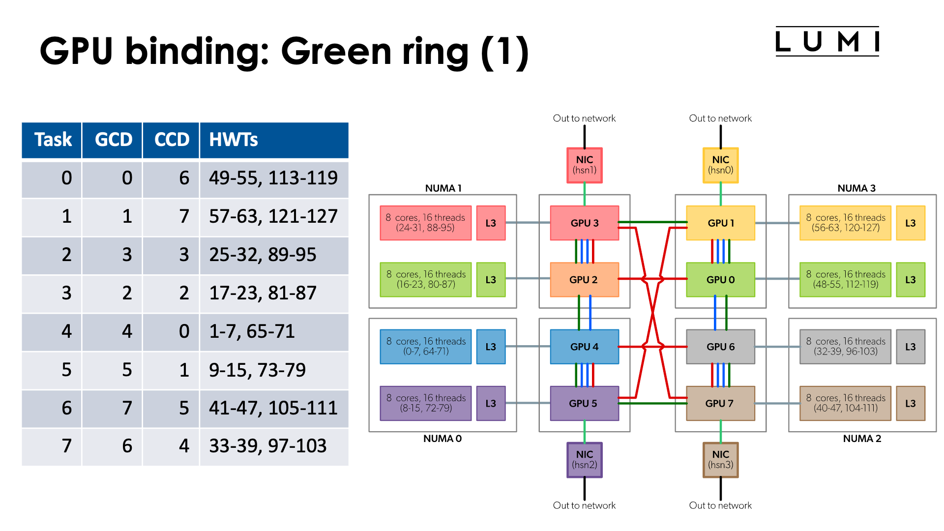
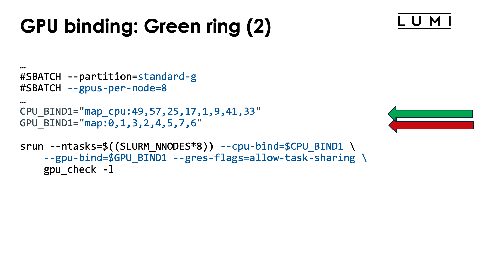
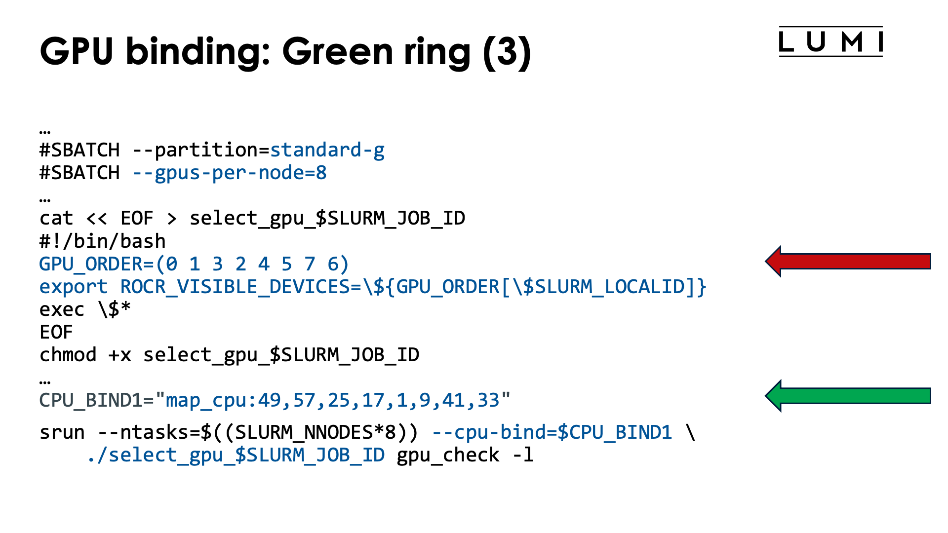
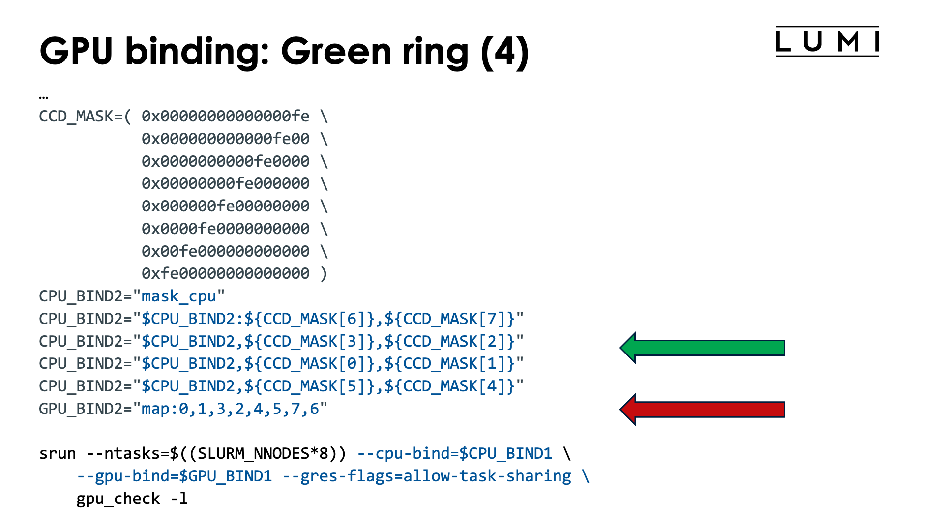
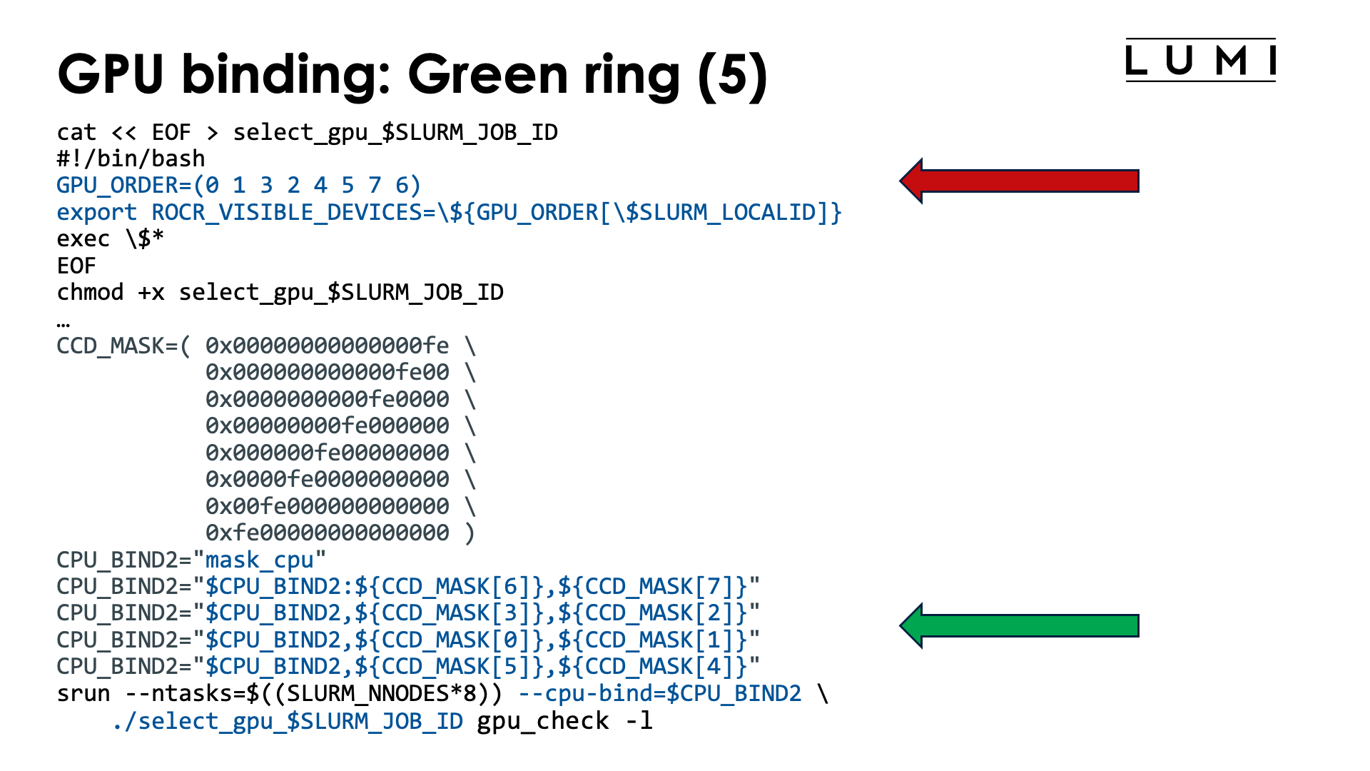
As a final example for whole node allocations, lets bind tasks such that the MPI ranks are mapped upon the green ring which is GCD 0 - 1 - 3 - 2 - 4 - 5 - 7 - 6 - 0. In other words, we want to create the mapping
| Task | GCD | CCD | Available cores | CPU mask (without HWTs) |
|---|---|---|---|---|
| 0 | 0 | 6 | 49-55, 113-119 | 0xfe000000000000 |
| 1 | 1 | 7 | 57-63, 121-127 | 0xfe00000000000000 |
| 2 | 3 | 3 | 25-32, 89-95 | 0xfe000000 |
| 3 | 2 | 2 | 17-23, 81-87 | 0xfe0000 |
| 4 | 4 | 0 | 1-7, 65-71 | 0xfe |
| 5 | 5 | 1 | 9-15, 73-79 | 0xfe00 |
| 6 | 7 | 5 | 41-47, 105-111 | 0xfe0000000000 |
| 7 | 6 | 4 | 33-39, 97-103 | 0xfe00000000 |
This mapping would be useful when using GPU-to-GPU communication in a scenario where task i only communicates with tasks i-1 and i+1 (modulo 8), so the communication pattern is a ring.
Now we need to reorder both the cores and the GCDs, so we basically combine the approach taken in the two scripts above:
#!/bin/bash
#SBATCH --account=project_46YXXXXXX
#SBATCH --job-name=map-ring-green
#SBATCH --output %x-%j.txt
#SBATCH --partition=standard-g
#SBATCH --gpus-per-node=8
#SBATCH --nodes=2
#SBATCH --time=5:00

module load LUMI/25.03 partition/G lumi-CPEtools/1.2-cpeCray-25.03-hpcat-0.9

# Mapping:
# | Task | GCD | CCD | Available cores | CPU mask (w/o HWTs) |
# |-----:|----:|----:|:----------------|--------------------:|
# |    0 |   0 |   6 | 49-55, 113-119  |   0xfe000000000000  |
# |    1 |   1 |   7 | 57-63, 121-127  | 0xfe00000000000000  |
# |    2 |   3 |   3 | 25-32, 89-95    |         0xfe000000  |
# |    3 |   2 |   2 | 17-23, 81-87    |           0xfe0000  |
# |    4 |   4 |   0 | 1-7, 65-71      |               0xfe  |
# |    5 |   5 |   1 | 9-15, 73-79     |             0xfe00  |
# |    6 |   7 |   5 | 41-47, 105-111  |     0xfe0000000000  |
# |    7 |   6 |   4 | 33-39, 97-103   |       0xfe00000000  |

# Mapping from column 2 (GCD)
GPU_BIND="map:0,1,3,2,4,5,7,6"

# Core order: Column 4 (Available cores)
CPU_BIND1="map_cpu:49,57,25,17,1,9,41,33"

# Mask: Column 5 of the table, top to bottom, or column 3 (CCD) for the trick we use here.
CCD_MASK=( 0x00000000000000fe \
           0x000000000000fe00 \
           0x0000000000fe0000 \
           0x00000000fe000000 \
           0x000000fe00000000 \
           0x0000fe0000000000 \
           0x00fe000000000000 \
           0xfe00000000000000 )
CPU_BIND2="mask_cpu"
CPU_BIND2="$CPU_BIND2:${CCD_MASK[6]},${CCD_MASK[7]}"
CPU_BIND2="$CPU_BIND2,${CCD_MASK[3]},${CCD_MASK[2]}"
CPU_BIND2="$CPU_BIND2,${CCD_MASK[0]},${CCD_MASK[1]}"
CPU_BIND2="$CPU_BIND2,${CCD_MASK[5]},${CCD_MASK[4]}"

export MPICH_GPU_SUPPORT_ENABLED=1
export MPICH_OFI_NIC_POLICY=GPU

echo -e "\nPure MPI:\n"
srun --ntasks=$((SLURM_NNODES*8)) --cpu-bind=$CPU_BIND1 \
    --gpu-bind=$GPU_BIND --gres-flags=allow-task-sharing \
    mpi_check -r
srun --ntasks=$((SLURM_NNODES*8)) --cpu-bind=$CPU_BIND1 \
    --gpu-bind=$GPU_BIND --gres-flags=allow-task-sharing \
    gpu_check -l

echo -e "\nHybrid:\n"
srun --ntasks=$((SLURM_NNODES*8)) --cpu-bind=$CPU_BIND2 \
    --gpu-bind=$GPU_BIND --gres-flags=allow-task-sharing \
    hybrid_check -r
srun --ntasks=$((SLURM_NNODES*8)) --cpu-bind=$CPU_BIND2 \
    --gpu-bind=$GPU_BIND --gres-flags=allow-task-sharing \
    gpu_check -l
The values for GPU_BIND are easily read from the second column of the table with the mapping
that we prepared. The cores to use for the pure MPI run are easily read from the fourth column of the table:
simply take the first core of each line. Finally, to build the mask,
we used some bash trickery. We first define the bash array CCD_MASK with the mask for each chiplet.
As this has a regular structure, this is easy to build. Then we compose the mask list for the CPUs
by indexing in that array, where the indices are easily read from the third column in the mapping table.
The alternative code to build CPU_BIND2 is
CPU_BIND2="mask_cpu"
CPU_BIND2="$CPU_BIND2:0x00fe000000000000,0xfe00000000000000"
CPU_BIND2="$CPU_BIND2,0x00000000fe000000,0x0000000000fe0000"
CPU_BIND2="$CPU_BIND2,0x00000000000000fe,0x000000000000fe00"
CPU_BIND2="$CPU_BIND2,0x0000fe0000000000,0x000000fe00000000"
which may be shorter, but requires some puzzling to build and hence is more prone to error. These values can be read from the last column of the table.
The output of the second srun command is now
MPI 000 - OMP 000 - HWT 049 (CCD6) - Node nid005083 - RT_GPU_ID 0 - GPU_ID 0 - Bus_ID c1(GCD0/CCD6)
MPI 001 - OMP 000 - HWT 057 (CCD7) - Node nid005083 - RT_GPU_ID 0 - GPU_ID 1 - Bus_ID c6(GCD1/CCD7)
MPI 002 - OMP 000 - HWT 025 (CCD3) - Node nid005083 - RT_GPU_ID 0 - GPU_ID 3 - Bus_ID cc(GCD3/CCD3)
MPI 003 - OMP 000 - HWT 017 (CCD2) - Node nid005083 - RT_GPU_ID 0 - GPU_ID 2 - Bus_ID c9(GCD2/CCD2)
MPI 004 - OMP 000 - HWT 001 (CCD0) - Node nid005083 - RT_GPU_ID 0 - GPU_ID 4 - Bus_ID d1(GCD4/CCD0)
MPI 005 - OMP 000 - HWT 009 (CCD1) - Node nid005083 - RT_GPU_ID 0 - GPU_ID 5 - Bus_ID d6(GCD5/CCD1)
MPI 006 - OMP 000 - HWT 041 (CCD5) - Node nid005083 - RT_GPU_ID 0 - GPU_ID 7 - Bus_ID dc(GCD7/CCD5)
MPI 007 - OMP 000 - HWT 033 (CCD4) - Node nid005083 - RT_GPU_ID 0 - GPU_ID 6 - Bus_ID d9(GCD6/CCD4)
Checking the last column, we see that the GCDs are indeed in the desired order for the green ring, and is is also easy to check that each task is also mapped on the optimal CCD for the GCD.
Job script with a wrapper script (click to expand)
#!/bin/bash
#SBATCH --account=project_46YXXXXXX
#SBATCH --job-name=map-ring-green-wrapper
#SBATCH --output %x-%j.txt
#SBATCH --partition=standard-g
#SBATCH --gpus-per-node=8
#SBATCH --nodes=2
#SBATCH --time=5:00

module load LUMI/25.03 partition/G lumi-CPEtools/1.2-cpeCray-25.03-hpcat-0.9

# Mapping:
# | Task | GCD | CCD | Available cores | CPU mask (w/o HWTs) |
# |-----:|----:|----:|:----------------|--------------------:|
# |    0 |   0 |   6 | 49-55, 113-119  |   0xfe000000000000  |
# |    1 |   1 |   7 | 57-63, 121-127  | 0xfe00000000000000  |
# |    2 |   3 |   3 | 25-32, 89-95    |         0xfe000000  |
# |    3 |   2 |   2 | 17-23, 81-87    |           0xfe0000  |
# |    4 |   4 |   0 | 1-7, 65-71      |               0xfe  |
# |    5 |   5 |   1 | 9-15, 73-79     |             0xfe00  |
# |    6 |   7 |   5 | 41-47, 105-111  |     0xfe0000000000  |
# |    7 |   6 |   4 | 33-39, 97-103   |       0xfe00000000  |

# Mapping from column 2 (GCD)
cat << EOF > select_gpu_$SLURM_JOB_ID
#!/bin/bash
# GPU order: Column 2 of the table
GPU_ORDER=(0 1 3 2 4 5 7 6)
export ROCR_VISIBLE_DEVICES=\${GPU_ORDER[\$SLURM_LOCALID]}
exec \$*
EOF
chmod +x select_gpu_$SLURM_JOB_ID

# Core order: Column 4 (Available cores)
CPU_BIND1="map_cpu:49,57,25,17,1,9,41,33"

# Mask: Column 5 of the table, top to bottom, or column 3 (CCD) for the trick we use here.
CCD_MASK=( 0x00000000000000fe \
           0x000000000000fe00 \
           0x0000000000fe0000 \
           0x00000000fe000000 \
           0x000000fe00000000 \
           0x0000fe0000000000 \
           0x00fe000000000000 \
           0xfe00000000000000 )
CPU_BIND2="mask_cpu"
CPU_BIND2="$CPU_BIND2:${CCD_MASK[6]},${CCD_MASK[7]}"
CPU_BIND2="$CPU_BIND2,${CCD_MASK[3]},${CCD_MASK[2]}"
CPU_BIND2="$CPU_BIND2,${CCD_MASK[0]},${CCD_MASK[1]}"
CPU_BIND2="$CPU_BIND2,${CCD_MASK[5]},${CCD_MASK[4]}"

export MPICH_GPU_SUPPORT_ENABLED=1
export MPICH_OFI_NIC_POLICY=GPU

echo -e "\nPure MPI:\n"
srun --ntasks=$((SLURM_NNODES*8)) --cpu-bind=$CPU_BIND1 ./select_gpu_$SLURM_JOB_ID mpi_check -r
srun --ntasks=$((SLURM_NNODES*8)) --cpu-bind=$CPU_BIND1 ./select_gpu_$SLURM_JOB_ID gpu_check -l

echo -e "\nHybrid:\n"
srun --ntasks=$((SLURM_NNODES*8)) --cpu-bind=$CPU_BIND2 ./select_gpu_$SLURM_JOB_ID hybrid_check -r
srun --ntasks=$((SLURM_NNODES*8)) --cpu-bind=$CPU_BIND2 ./select_gpu_$SLURM_JOB_ID gpu_check -l

/bin/rm -f select_gpu_$SLURM_JOB_ID
Just as for GPU_BIND in the previous example, the values for GPU_ORDER are easily read from
the second column of the table with the mapping that we prepared.
Job script with some more advanced bash (click to expand)
#!/bin/bash
#SBATCH --account=project_46YXXXXXX
#SBATCH --job-name=map-advanced-multiple
#SBATCH --output %x-%j.txt
#SBATCH --partition=standard-g
#SBATCH --gpus-per-node=8
#SBATCH --nodes=1
#SBATCH --time=5:00

module load LUMI/25.03 partition/G lumi-CPEtools/1.2-cpeCray-25.03-hpcat-0.9

#
# Define the core mask for a single CCD. In this case, we use binary notation
# as that is even easier to interpret.
#
coremask='2#00000010'  # Can use the binary representation, hexadecimal with 0x, or decimal

#
# Some mappings, specified as the order of the GCDs (and spaces are essential):
#
linear_CCD="4 5 2 3 6 7 0 1"
linear_GCD="0 1 2 3 4 5 6 7"
ring_green="0 1 3 2 4 5 7 6"
ring_red="0 1 5 4 6 7 3 2"

#
# run_gpu script, takes the string with GCDs as the first argument.
#
cat << EOF > run_gpu_$SLURM_JOB_ID
#!/bin/bash
GCD_ORDER=( \$1 )
shift
export ROCR_VISIBLE_DEVICES=\${GCD_ORDER[\$SLURM_LOCALID]}
exec "\$@"
EOF
chmod +x run_gpu_$SLURM_JOB_ID

#
# Build the CPU binding
# Argument one is mask, all other arguments are treated as an array of GCD numbers.
#

function generate_mask {

    # First argument is the mask for CCD0
    mask=$1

    # Other arguments are either a string already with the GCDs, or just one GCD per argument.
    shift
    GCDs=( "$@" )
    # Fully expand (doesn't matter as the loop can deal with it, but good if we want to check the number)
    GCDs=( ${GCDs[@]} )

    # For each GCD, the corresponding CCD number in the optimal mapping.
    # So first element is the CCD number for GCD0, second is the CCD number for GCD1, etc.
    MAP_to_CCD=( 6 7 2 3 0 1 4 5 )

    CPU_BIND=""

    # Loop over the GCDs in the order of the list to compute the corresponding
    # CPU mask.
    for GCD in ${GCDs[@]}
    do
        # Get the matching CCD for this GCD
        CCD=${MAP_to_CCD[$GCD]}

        # Shift the mask for CCD0 to the position for CCD $CCD
        printf -v tmpvar "0x%016x" $((mask << $((CCD*8))))

        # Add to CPU_BIND. We'll remove the leading , this creates later.
        CPU_BIND="$CPU_BIND,$tmpvar"
    done

    # Strip the leading ,
    CPU_BIND="${CPU_BIND#,}"

    # Return the result by printing to stdout
    printf "$CPU_BIND"

}

#
# Running the check programs
#

export MPICH_GPU_SUPPORT_ENABLED=1
export MPICH_OFI_NIC_POLICY=GPU

echo -e "\nTest runs:\n"

# Use either "hpcat" or "gpu_check -l"
exe="gpu_check -l"

echo -e "\nConsecutive CCDs:\n"
# Without wrapper
echo -e "- Without wrapper\n"
srun --ntasks=$((SLURM_NNODES*8)) \
     --cpu-bind=mask_cpu:$(generate_mask $coremask $linear_CCD) \
     --gpu-bind=map:${linear_CCD// /,} --gres-flags=allow-task-sharing \
     $exe
# With wrapper
echo -e "\n- With wrapper\n"
srun --ntasks=$((SLURM_NNODES*8)) \
     --cpu-bind=mask_cpu:$(generate_mask $coremask $linear_CCD) \
     ./run_gpu_$SLURM_JOB_ID "$linear_CCD" $exe

echo -e "\nConsecutive GCDs:\n"
# Without wrapper
echo -e "- Without wrapper\n"
srun --ntasks=$((SLURM_NNODES*8)) \
     --cpu-bind=mask_cpu:$(generate_mask $coremask $linear_GCD) \
     --gpu-bind=map:${linear_GCD// /,} --gres-flags=allow-task-sharing \
     $exe
# With wrapper
echo -e "\n- With wrapper\n"
srun --ntasks=$((SLURM_NNODES*8)) \
     --cpu-bind=mask_cpu:$(generate_mask $coremask $linear_GCD) \
     ./run_gpu_$SLURM_JOB_ID "$linear_GCD" $exe

echo -e "\nGreen ring:\n"
# Without wrapper
echo -e "- Without wrapper\n"
srun --ntasks=$((SLURM_NNODES*8)) \
     --cpu-bind=mask_cpu:$(generate_mask $coremask $ring_green) \
     --gpu-bind=map:${ring_green// /,} --gres-flags=allow-task-sharing \
     $exe
# With wrapper
echo -e "\n- With wrapper\n"
srun --ntasks=$((SLURM_NNODES*8)) \
     --cpu-bind=mask_cpu:$(generate_mask $coremask $ring_green) \
     ./run_gpu_$SLURM_JOB_ID "$ring_green" $exe

echo -e "\nRed ring:\n"
# Without wrapper
echo -e "- Without wrapper\n"
srun --ntasks=$((SLURM_NNODES*8)) \
     --cpu-bind=mask_cpu:$(generate_mask $coremask $ring_red) \
     --gpu-bind=map:${ring_red// /,} --gres-flags=allow-task-sharing \
     $exe
# With wrapper
echo -e "\n- With wrapper\n"
srun --ntasks=$((SLURM_NNODES*8)) \
     --cpu-bind=mask_cpu:$(generate_mask $coremask $ring_red) \
     ./run_gpu_$SLURM_JOB_ID "$ring_red" $exe

echo -e "\nFirst two CPU NUMA domains (assuming one node in the allocation):\n"
half="4 5 2 3"
# Without wrapper
echo -e "- Without wrapper\n"
srun --ntasks=4 \
     --cpu-bind=mask_cpu:$(generate_mask $coremask $half) \
     --gpu-bind=map:${half// /,} --gres-flags=allow-task-sharing \
     $exe
# With wrapper
echo -e "\n- With wrapper\n"
srun --ntasks=4 \
     --cpu-bind=mask_cpu:$(generate_mask $coremask $half) \
     ./run_gpu_$SLURM_JOB_ID "$half" $exe

/bin/rm -f run_gpu_$SLURM_JOB_ID
In this script, we have modified the and renamed the usual select_gpu script (renamed to run_cpu) to take
as the first argument a string with a space-separated list of the GCDs to use. This has
been combined with the bash function generate_mask (which could have been transformed in a script as well)
that computes the CPU mask starting from the mask for CCD0 and shifting that mask as needed.
The input is the mask to use and then the GCDs to use, either as a single string or as a
series of arguments (e.g., resulting from an array expansion).
Both commands are then combined in the srun command. The generate_mask function is used to generate
the mask for --gpu-bind while the run_gpu script is used to set ROCR_VISIBLE_DEVICES for each task.
The examples also show how easy it is to experiment with different mappings. The one limitation of the
script and function is that there can be only 1 GPU per task and one task per GPU, and the CPU mask is also
limited to a single CCD (which makes sense with the GPU restriction). Generating masks that also include the
second hardware thread is not supported yet. (We use bash arithmetic internally which is limited to 64-bit integers).
We've also included the srun commands without the wrapper script for GPU binding.
What about "allocate by resources" partitions?

On partitions that are "allocatable by resource", e.g., small-g, you are never guaranteed that tasks
will be spread in a reasonable way over the CCDs and that the matching GPUs will be available to your job.
Creating an optimal mapping or taking the topology into account is hence impossible.
What is possible though is work around the fact that with the usual options for such resource allocations,
Slurm will lock up the GPUs for individual tasks in control groups so that the Peer2Peer IPC intra-node
communication mechanism has to be turned off. We can do this for job steps that follow the pattern of
resources allocated via the sbatch arguments (usually #SBATCH lines), and then proceed in two different ways:
-
By far the easiest way is to simply use
--gres-flags=allow-task-sharing. -
There is an alternative but more complicated approach which isn't really needed anymore since the January 2026 system update, but we leave it here in case issues with the first approach would still show up:
-
We can turn off the Slurm GPU binding mechanism with
--gpu-bind=none. -
Even then, the GPUs will still be locked up in a control group on each node for the job and hence on each node be numbered starting from zero.
-
And each task also has a local ID that can be used to map the appropriate number of GPUs to each task. Now we have to use a wrapper script though or some clever bash syntax:
-
This can be demonstrated with the following job script:
#! /bin/bash
#SBATCH --account=project_46YXXXXXX
#SBATCH --job-name=map-smallg-1gpt
#SBATCH --output %x-%j.txt
#SBATCH --partition=small-g
#SBATCH --ntasks=12
#SBATCH --cpus-per-task=2
#SBATCH --gpus-per-task=1
#SBATCH --hint=nomultithread
#SBATCH --time=5:00

module load LUMI/25.03 partition/G lumi-CPEtools/1.2-cpeCray-25.03-hpcat-0.9

cat << EOF > select_gpu_$SLURM_JOB_ID
#!/bin/bash
export ROCR_VISIBLE_DEVICES=\$SLURM_LOCALID
exec \$*
EOF
chmod +x ./select_gpu_$SLURM_JOB_ID

echo -e "\nCase 1: Bad case without any --gpu-bind nor --gres-flags\n"
set -x
srun gpu_check -l
srun --label rocm-smi | sort -s -n
set +x

echo -e "\nCase 2: With --gres-flags=allow-task-sharing\n"
set -x
srun --gres-flags=allow-task-sharing gpu_check -l
srun --label --gres-flags=allow-task-sharing rocm-smi | sort -s -n
set +x

echo -e "\nCase 3: With --gpu-bind=none and select_gpu script\n"
set -x
srun --gpu-bind=none ./select_gpu_$SLURM_JOB_ID gpu_check -l
srun --label --gpu-bind=none ./select_gpu_$SLURM_JOB_ID rocm-smi | sort -s -n
set +x

echo -e "\nCase 4: With --gpu-bind=none and some bash in the command\n"
set -x
srun --gpu-bind=none bash -c "ROCR_VISIBLE_DEVICES=\$SLURM_LOCALID gpu_check -l"
srun --gpu-bind=none --label bash -c "ROCR_VISIBLE_DEVICES=\$SLURM_LOCALID rocm-smi" | sort -s -n
set +x

/bin/rm -f select_gpu_$SLURM_JOB_ID
To run this job successfully, we need 12 GPUs so obviously the tasks will be spread over more than one node. The output below is not reproducible as the way the tasks are spread over nodes will differ for every run.
The output of the first srun command (without any --gpu-bind and without
--gres-flags=allow-task-sharing):
+ srun gpu_check -l
MPI 000 - OMP 000 - HWT 001 (CCD0) - Node nid005080 - RT_GPU_ID 0 - GPU_ID 0 - Bus_ID d1(GCD4/CCD0)
MPI 000 - OMP 001 - HWT 002 (CCD0) - Node nid005080 - RT_GPU_ID 0 - GPU_ID 0 - Bus_ID d1(GCD4/CCD0)
MPI 001 - OMP 000 - HWT 044 (CCD5) - Node nid005080 - RT_GPU_ID 0 - GPU_ID 0 - Bus_ID de(GCD7/CCD5)
MPI 001 - OMP 001 - HWT 045 (CCD5) - Node nid005080 - RT_GPU_ID 0 - GPU_ID 0 - Bus_ID de(GCD7/CCD5)
MPI 002 - OMP 000 - HWT 001 (CCD0) - Node nid007880 - RT_GPU_ID 0 - GPU_ID 0 - Bus_ID d1(GCD4/CCD0)
MPI 002 - OMP 001 - HWT 002 (CCD0) - Node nid007880 - RT_GPU_ID 0 - GPU_ID 0 - Bus_ID d1(GCD4/CCD0)
MPI 003 - OMP 000 - HWT 009 (CCD1) - Node nid007880 - RT_GPU_ID 0 - GPU_ID 0 - Bus_ID d6(GCD5/CCD1)
MPI 003 - OMP 001 - HWT 010 (CCD1) - Node nid007880 - RT_GPU_ID 0 - GPU_ID 0 - Bus_ID d6(GCD5/CCD1)
MPI 004 - OMP 000 - HWT 017 (CCD2) - Node nid007880 - RT_GPU_ID 0 - GPU_ID 0 - Bus_ID c9(GCD2/CCD2)
MPI 004 - OMP 001 - HWT 018 (CCD2) - Node nid007880 - RT_GPU_ID 0 - GPU_ID 0 - Bus_ID c9(GCD2/CCD2)
MPI 005 - OMP 000 - HWT 025 (CCD3) - Node nid007880 - RT_GPU_ID 0 - GPU_ID 0 - Bus_ID ce(GCD3/CCD3)
MPI 005 - OMP 001 - HWT 026 (CCD3) - Node nid007880 - RT_GPU_ID 0 - GPU_ID 0 - Bus_ID ce(GCD3/CCD3)
MPI 006 - OMP 000 - HWT 033 (CCD4) - Node nid007880 - RT_GPU_ID 0 - GPU_ID 0 - Bus_ID d9(GCD6/CCD4)
MPI 006 - OMP 001 - HWT 034 (CCD4) - Node nid007880 - RT_GPU_ID 0 - GPU_ID 0 - Bus_ID d9(GCD6/CCD4)
MPI 007 - OMP 000 - HWT 041 (CCD5) - Node nid007880 - RT_GPU_ID 0 - GPU_ID 0 - Bus_ID de(GCD7/CCD5)
MPI 007 - OMP 001 - HWT 042 (CCD5) - Node nid007880 - RT_GPU_ID 0 - GPU_ID 0 - Bus_ID de(GCD7/CCD5)
MPI 008 - OMP 000 - HWT 049 (CCD6) - Node nid007880 - RT_GPU_ID 0 - GPU_ID 0 - Bus_ID c1(GCD0/CCD6)
MPI 008 - OMP 001 - HWT 050 (CCD6) - Node nid007880 - RT_GPU_ID 0 - GPU_ID 0 - Bus_ID c1(GCD0/CCD6)
MPI 009 - OMP 000 - HWT 057 (CCD7) - Node nid007880 - RT_GPU_ID 0 - GPU_ID 0 - Bus_ID c6(GCD1/CCD7)
MPI 009 - OMP 001 - HWT 058 (CCD7) - Node nid007880 - RT_GPU_ID 0 - GPU_ID 0 - Bus_ID c6(GCD1/CCD7)
MPI 010 - OMP 000 - HWT 017 (CCD2) - Node nid007895 - RT_GPU_ID 0 - GPU_ID 0 - Bus_ID c9(GCD2/CCD2)
MPI 010 - OMP 001 - HWT 018 (CCD2) - Node nid007895 - RT_GPU_ID 0 - GPU_ID 0 - Bus_ID c9(GCD2/CCD2)
MPI 011 - OMP 000 - HWT 041 (CCD5) - Node nid007895 - RT_GPU_ID 0 - GPU_ID 0 - Bus_ID de(GCD7/CCD5)
MPI 011 - OMP 001 - HWT 042 (CCD5) - Node nid007895 - RT_GPU_ID 0 - GPU_ID 0 - Bus_ID de(GCD7/CCD5)
In this case, we got tasks on 3 different nodes: The first two tasks are on the same node, the
next 8 are on another node and the last two are on yet another node. We were lucky and got each
task on a set of two cores that also matched with the GCD. However, we see that each task
got ROCR_VISIBLE_DEVICES set to 0 (the GPU_ID field) which indicates that each task sees only
one GPU because it is locked up in a task cgroup.
This is confirmed when we look at the output of rocm-smi sorted per task:
+ srun --label rocm-smi
+ sort -s -n
srun: Step created for StepId=17296508.1
 0:
 0:
 0: ========================================== ROCm System Management Interface ==========================================
 0: ==================================================== Concise Info ====================================================
 0: Device  Node  IDs              Temp    Power   Partitions          SCLK    MCLK     Fan  Perf    PwrCap  VRAM%  GPU%
 0:               (DID,     GUID)  (Edge)  (Avg)   (Mem, Compute, ID)
 0: ======================================================================================================================
 0: 0       8     0x7408,   13395  46.0°C  102.0W  N/A, N/A, 0         800Mhz  1600Mhz  0%   manual  500.0W  0%     0%
 0: ======================================================================================================================
 0: ================================================ End of ROCm SMI Log =================================================
 1:
 1:
 1: ========================================== ROCm System Management Interface ==========================================
 1: ==================================================== Concise Info ====================================================
 1: Device  Node  IDs              Temp    Power  Partitions          SCLK    MCLK     Fan  Perf    PwrCap  VRAM%  GPU%
 1:               (DID,     GUID)  (Edge)  (Avg)  (Mem, Compute, ID)
 1: ======================================================================================================================
 1: 0       11    0x7408,   49174  44.0°C  N/A    N/A, N/A, 0         800Mhz  1600Mhz  0%   manual  0.0W    0%     0%
 1: ======================================================================================================================
 1: ================================================ End of ROCm SMI Log =================================================
 2:
 2:
 2: ========================================== ROCm System Management Interface ==========================================
 2: ==================================================== Concise Info ====================================================
 2: Device  Node  IDs              Temp    Power  Partitions          SCLK    MCLK     Fan  Perf    PwrCap  VRAM%  GPU%
 2:               (DID,     GUID)  (Edge)  (Avg)  (Mem, Compute, ID)
 2: ======================================================================================================================
 2: 0       8     0x7408,   13395  44.0°C  89.0W  N/A, N/A, 0         800Mhz  1600Mhz  0%   manual  500.0W  0%     0%
 2: ======================================================================================================================
 2: ================================================ End of ROCm SMI Log =================================================
...
We only show the output for the first 3 MPI ranks. Notice that each of the tasks sees only one GPU which is due to the task-specific cgroups and this confirms that some types of inter-GPU communication will not work.
You can also use rocm-smi --showbus if you prefer to compare the PCIe IDs of each GPU also with the
values reported by gpu_check -l.
The second srun is the way we would advise to work, i.e., simply use
--gres-flags=allow-task-sharing, which results in::
+ srun --gres-flags=allow-task-sharing gpu_check -l
srun: Step created for StepId=17296508.2
MPI 000 - OMP 000 - HWT 001 (CCD0) - Node nid005080 - RT_GPU_ID 0 - GPU_ID 0 - Bus_ID d1(GCD4/CCD0)
MPI 000 - OMP 001 - HWT 002 (CCD0) - Node nid005080 - RT_GPU_ID 0 - GPU_ID 0 - Bus_ID d1(GCD4/CCD0)
MPI 001 - OMP 000 - HWT 044 (CCD5) - Node nid005080 - RT_GPU_ID 0 - GPU_ID 1 - Bus_ID de(GCD7/CCD5)
MPI 001 - OMP 001 - HWT 045 (CCD5) - Node nid005080 - RT_GPU_ID 0 - GPU_ID 1 - Bus_ID de(GCD7/CCD5)
MPI 002 - OMP 000 - HWT 001 (CCD0) - Node nid007880 - RT_GPU_ID 0 - GPU_ID 0 - Bus_ID c1(GCD0/CCD6)
MPI 002 - OMP 001 - HWT 002 (CCD0) - Node nid007880 - RT_GPU_ID 0 - GPU_ID 0 - Bus_ID c1(GCD0/CCD6)
MPI 003 - OMP 000 - HWT 009 (CCD1) - Node nid007880 - RT_GPU_ID 0 - GPU_ID 1 - Bus_ID c6(GCD1/CCD7)
MPI 003 - OMP 001 - HWT 010 (CCD1) - Node nid007880 - RT_GPU_ID 0 - GPU_ID 1 - Bus_ID c6(GCD1/CCD7)
MPI 004 - OMP 000 - HWT 017 (CCD2) - Node nid007880 - RT_GPU_ID 0 - GPU_ID 2 - Bus_ID c9(GCD2/CCD2)
MPI 004 - OMP 001 - HWT 018 (CCD2) - Node nid007880 - RT_GPU_ID 0 - GPU_ID 2 - Bus_ID c9(GCD2/CCD2)
MPI 005 - OMP 000 - HWT 025 (CCD3) - Node nid007880 - RT_GPU_ID 0 - GPU_ID 3 - Bus_ID ce(GCD3/CCD3)
MPI 005 - OMP 001 - HWT 026 (CCD3) - Node nid007880 - RT_GPU_ID 0 - GPU_ID 3 - Bus_ID ce(GCD3/CCD3)
MPI 006 - OMP 000 - HWT 033 (CCD4) - Node nid007880 - RT_GPU_ID 0 - GPU_ID 4 - Bus_ID d1(GCD4/CCD0)
MPI 006 - OMP 001 - HWT 034 (CCD4) - Node nid007880 - RT_GPU_ID 0 - GPU_ID 4 - Bus_ID d1(GCD4/CCD0)
MPI 007 - OMP 000 - HWT 041 (CCD5) - Node nid007880 - RT_GPU_ID 0 - GPU_ID 5 - Bus_ID d6(GCD5/CCD1)
MPI 007 - OMP 001 - HWT 042 (CCD5) - Node nid007880 - RT_GPU_ID 0 - GPU_ID 5 - Bus_ID d6(GCD5/CCD1)
MPI 008 - OMP 000 - HWT 049 (CCD6) - Node nid007880 - RT_GPU_ID 0 - GPU_ID 6 - Bus_ID d9(GCD6/CCD4)
MPI 008 - OMP 001 - HWT 050 (CCD6) - Node nid007880 - RT_GPU_ID 0 - GPU_ID 6 - Bus_ID d9(GCD6/CCD4)
MPI 009 - OMP 000 - HWT 057 (CCD7) - Node nid007880 - RT_GPU_ID 0 - GPU_ID 7 - Bus_ID de(GCD7/CCD5)
MPI 009 - OMP 001 - HWT 058 (CCD7) - Node nid007880 - RT_GPU_ID 0 - GPU_ID 7 - Bus_ID de(GCD7/CCD5)
MPI 010 - OMP 000 - HWT 017 (CCD2) - Node nid007895 - RT_GPU_ID 0 - GPU_ID 0 - Bus_ID c9(GCD2/CCD2)
MPI 010 - OMP 001 - HWT 018 (CCD2) - Node nid007895 - RT_GPU_ID 0 - GPU_ID 0 - Bus_ID c9(GCD2/CCD2)
MPI 011 - OMP 000 - HWT 041 (CCD5) - Node nid007895 - RT_GPU_ID 0 - GPU_ID 1 - Bus_ID de(GCD7/CCD5)
MPI 011 - OMP 001 - HWT 042 (CCD5) - Node nid007895 - RT_GPU_ID 0 - GPU_ID 1 - Bus_ID de(GCD7/CCD5)
The important change is now in the GPU_ID field: We now see different values there,
indicating that each task on each node sees all the GPUs available to the task on the node.
We do loose the correct CPU-GPU mapping though. On the two nodes where we got only 2 GPUs, we
are still lucky and got a good mapping (but this is not guaranteed!) but on the full node that
got and that runs MPI rand 2 till 9, the mapping is no longer correct as the task with local
ID i got 2 cores on CCD i and got GCD i.
The output of the rocm-smi command for the first three tasks is:
+ srun --label --gres-flags=allow-task-sharing rocm-smi
+ sort -s -n
 0:
 0:
 0: ========================================== ROCm System Management Interface ==========================================
 0: ==================================================== Concise Info ====================================================
 0: Device  Node  IDs              Temp    Power   Partitions          SCLK    MCLK     Fan  Perf    PwrCap  VRAM%  GPU%
 0:               (DID,     GUID)  (Edge)  (Avg)   (Mem, Compute, ID)
 0: ======================================================================================================================
 0: 0       8     0x7408,   13395  46.0°C  102.0W  N/A, N/A, 0         800Mhz  1600Mhz  0%   manual  500.0W  0%     0%
 0: 1       11    0x7408,   49174  43.0°C  N/A     N/A, N/A, 0         800Mhz  1600Mhz  0%   manual  0.0W    0%     0%
 0: ======================================================================================================================
 0: ================================================ End of ROCm SMI Log =================================================
 1:
 1:
 1: ========================================== ROCm System Management Interface ==========================================
 1: ==================================================== Concise Info ====================================================
 1: Device  Node  IDs              Temp    Power   Partitions          SCLK    MCLK     Fan  Perf    PwrCap  VRAM%  GPU%
 1:               (DID,     GUID)  (Edge)  (Avg)   (Mem, Compute, ID)
 1: ======================================================================================================================
 1: 0       8     0x7408,   13395  46.0°C  102.0W  N/A, N/A, 0         800Mhz  1600Mhz  0%   manual  500.0W  0%     0%
 1: 1       11    0x7408,   49174  43.0°C  N/A     N/A, N/A, 0         800Mhz  1600Mhz  0%   manual  0.0W    0%     0%
 1: ======================================================================================================================
 1: ================================================ End of ROCm SMI Log =================================================
 2:
 2:
 2: ========================================== ROCm System Management Interface ==========================================
 2: ==================================================== Concise Info ====================================================
 2: Device  Node  IDs              Temp    Power  Partitions          SCLK    MCLK     Fan  Perf    PwrCap  VRAM%  GPU%
 2:               (DID,     GUID)  (Edge)  (Avg)  (Mem, Compute, ID)
 2: ======================================================================================================================
 2: 0       4     0x7408,   63582  39.0°C  90.0W  N/A, N/A, 0         800Mhz  1600Mhz  0%   manual  500.0W  0%     0%
 2: 1       5     0x7408,   51740  47.0°C  N/A    N/A, N/A, 0         800Mhz  1600Mhz  0%   manual  0.0W    0%     0%
 2: 2       6     0x7408,   15961  41.0°C  93.0W  N/A, N/A, 0         800Mhz  1600Mhz  0%   manual  500.0W  0%     0%
 2: 3       7     0x7408,   3099   44.0°C  N/A    N/A, N/A, 0         800Mhz  1600Mhz  0%   manual  0.0W    0%     0%
 2: 4       8     0x7408,   13395  44.0°C  91.0W  N/A, N/A, 0         800Mhz  1600Mhz  0%   manual  500.0W  0%     0%
 2: 5       9     0x7408,   1553   45.0°C  N/A    N/A, N/A, 0         800Mhz  1600Mhz  0%   manual  0.0W    0%     0%
 2: 6       10    0x7408,   62036  40.0°C  83.0W  N/A, N/A, 0         800Mhz  1600Mhz  0%   manual  500.0W  0%     0%
 2: 7       11    0x7408,   49174  45.0°C  N/A    N/A, N/A, 0         800Mhz  1600Mhz  0%   manual  0.0W    0%     0%
 2: ======================================================================================================================
 2: ================================================ End of ROCm SMI Log =================================================
The first two tasks see two GCDs (and actually the same ones), so both GCDs available to the job on that node. The third task runs on a node that runs 8 tasks of the job and we see that there are also 8 GCDs available to the task. This confirms that the peer-2-peer communication mechanism that is preferred by RCCL and MPI for best performance will indeed work now.
The output of the next two blocks of the job script is not shown here, but is essentially the same as that for the second block: Communication will work, but the mapping between cores and GCDs is not optimal. Unfortunately, as we cannot know how many tasks will land on each node or if we will have full nodes somewhere, we cannot change that easily. The mechanisms in Slurm that should take care of properly mapping cores and GCDs are still buggy after the January 2026 system update.
Example job script when using 2 GPUs per task (click to expand)
#! /bin/bash
#SBATCH --job-name=map-smallg-2gpt
#SBATCH --output %x-%j.txt
#SBATCH --partition=small-g
#SBATCH --ntasks=6
#SBATCH --cpus-per-task=2
#SBATCH --gpus-per-task=2
#SBATCH --hint=nomultithread
#SBATCH --time=5:00

module load LUMI/25.03 partition/G lumi-CPEtools/1.2-cpeCray-25.03-hpcat-0.9

cat << EOF > select_gpu_$SLURM_JOB_ID
#!/bin/bash
export ROCR_VISIBLE_DEVICES=\$((SLURM_LOCALID*2)),\$((SLURM_LOCALID*2+1))
exec \$*
EOF
chmod +x ./select_gpu_$SLURM_JOB_ID


echo -e "\nCase 1: Bad case without any --gpu-bind nor --gres-flags\n"
set -x
srun gpu_check -l
srun --label rocm-smi | sort -s -n
set +x

echo -e "\nCase 2: With --gres-flags=allow-task-sharing\n"
set -x
srun --gres-flags=allow-task-sharing gpu_check -l
srun --label --gres-flags=allow-task-sharing rocm-smi | sort -s -n
set +x

echo -e "\nCase 3: With --gpu-bind=none and select_gpu script\n"
set -x
srun --gpu-bind=none ./select_gpu_$SLURM_JOB_ID gpu_check -l
srun --label --gpu-bind=none ./select_gpu_$SLURM_JOB_ID rocm-smi | sort -s -n
set +x

echo -e "\nCase 4: With --gpu-bind=none and some bash in the command\n"
set -x
srun --gpu-bind=none bash -c \
    "ROCR_VISIBLE_DEVICES=\$((SLURM_LOCALID*2)),\$((SLURM_LOCALID*2+1)) gpu_check -l"
srun --label --gpu-bind=none bash -c \
    "ROCR_VISIBLE_DEVICES=\$((SLURM_LOCALID*2)),\$((SLURM_LOCALID*2+1)) rocm-smi" | sort -s -n
set +x

/bin/rm -f select_gpu_$SLURM_JOB_ID
The changes that were required are only minimal. We now assign 2 GPUs to ROCR_VISIBLE_DEVICES which
is easily done with some bash arithmetic.
You will now see that the gpu_check in the first block will return the same twwo values for GPU_ID
for all tasks, even if these tasks run on the same node, and rocm-smi will confirm that there are only
two GCDs visible to each task, confirming they are locked-up in task-specific cgroups which will break
certain peer-2-peer communication mechanisms and cause issues in RCCL and MPI. For our run, gpu_check -l
produced:
+ srun gpu_check -l
MPI 000 - OMP 000 - HWT 001 (CCD0) - Node nid005109 - RT_GPU_ID 0,1 - GPU_ID 0,1 - Bus_ID d1(GCD4/CCD0),d6(GCD5/CCD1)
MPI 000 - OMP 001 - HWT 009 (CCD1) - Node nid005109 - RT_GPU_ID 0,1 - GPU_ID 0,1 - Bus_ID d1(GCD4/CCD0),d6(GCD5/CCD1)
MPI 001 - OMP 000 - HWT 017 (CCD2) - Node nid005109 - RT_GPU_ID 0,1 - GPU_ID 0,1 - Bus_ID c9(GCD2/CCD2),ce(GCD3/CCD3)
MPI 001 - OMP 001 - HWT 025 (CCD3) - Node nid005109 - RT_GPU_ID 0,1 - GPU_ID 0,1 - Bus_ID c9(GCD2/CCD2),ce(GCD3/CCD3)
MPI 002 - OMP 000 - HWT 033 (CCD4) - Node nid005109 - RT_GPU_ID 0,1 - GPU_ID 0,1 - Bus_ID d9(GCD6/CCD4),de(GCD7/CCD5)
MPI 002 - OMP 001 - HWT 041 (CCD5) - Node nid005109 - RT_GPU_ID 0,1 - GPU_ID 0,1 - Bus_ID d9(GCD6/CCD4),de(GCD7/CCD5)
MPI 003 - OMP 000 - HWT 049 (CCD6) - Node nid005109 - RT_GPU_ID 0,1 - GPU_ID 0,1 - Bus_ID c1(GCD0/CCD6),c6(GCD1/CCD7)
MPI 003 - OMP 001 - HWT 057 (CCD7) - Node nid005109 - RT_GPU_ID 0,1 - GPU_ID 0,1 - Bus_ID c1(GCD0/CCD6),c6(GCD1/CCD7)
MPI 004 - OMP 000 - HWT 001 (CCD0) - Node nid005111 - RT_GPU_ID 0,1 - GPU_ID 0,1 - Bus_ID d1(GCD4/CCD0),d6(GCD5/CCD1)
MPI 004 - OMP 001 - HWT 009 (CCD1) - Node nid005111 - RT_GPU_ID 0,1 - GPU_ID 0,1 - Bus_ID d1(GCD4/CCD0),d6(GCD5/CCD1)
MPI 005 - OMP 000 - HWT 017 (CCD2) - Node nid005111 - RT_GPU_ID 0,1 - GPU_ID 0,1 - Bus_ID c9(GCD2/CCD2),ce(GCD3/CCD3)
MPI 005 - OMP 001 - HWT 025 (CCD3) - Node nid005111 - RT_GPU_ID 0,1 - GPU_ID 0,1 - Bus_ID c9(GCD2/CCD2),ce(GCD3/CCD3)
The mapping between cores and GCDs was actually great, but this is of little use if communication issues hamper performance.
For the second case, you will see two different values for GPU_ID for the two tasks on a node.
We got:
+ srun --gres-flags=allow-task-sharing gpu_check -l
MPI 000 - OMP 000 - HWT 001 (CCD0) - Node nid005109 - RT_GPU_ID 0,1 - GPU_ID 0,1 - Bus_ID c1(GCD0/CCD6),c6(GCD1/CCD7)
MPI 000 - OMP 001 - HWT 009 (CCD1) - Node nid005109 - RT_GPU_ID 0,1 - GPU_ID 0,1 - Bus_ID c1(GCD0/CCD6),c6(GCD1/CCD7)
MPI 001 - OMP 000 - HWT 017 (CCD2) - Node nid005109 - RT_GPU_ID 0,1 - GPU_ID 2,3 - Bus_ID c9(GCD2/CCD2),ce(GCD3/CCD3)
MPI 001 - OMP 001 - HWT 025 (CCD3) - Node nid005109 - RT_GPU_ID 0,1 - GPU_ID 2,3 - Bus_ID c9(GCD2/CCD2),ce(GCD3/CCD3)
MPI 002 - OMP 000 - HWT 033 (CCD4) - Node nid005109 - RT_GPU_ID 0,1 - GPU_ID 4,5 - Bus_ID d1(GCD4/CCD0),d6(GCD5/CCD1)
MPI 002 - OMP 001 - HWT 041 (CCD5) - Node nid005109 - RT_GPU_ID 0,1 - GPU_ID 4,5 - Bus_ID d1(GCD4/CCD0),d6(GCD5/CCD1)
MPI 003 - OMP 000 - HWT 049 (CCD6) - Node nid005109 - RT_GPU_ID 0,1 - GPU_ID 6,7 - Bus_ID d9(GCD6/CCD4),de(GCD7/CCD5)
MPI 003 - OMP 001 - HWT 057 (CCD7) - Node nid005109 - RT_GPU_ID 0,1 - GPU_ID 6,7 - Bus_ID d9(GCD6/CCD4),de(GCD7/CCD5)
MPI 004 - OMP 000 - HWT 001 (CCD0) - Node nid005111 - RT_GPU_ID 0,1 - GPU_ID 0,1 - Bus_ID c9(GCD2/CCD2),ce(GCD3/CCD3)
MPI 004 - OMP 001 - HWT 009 (CCD1) - Node nid005111 - RT_GPU_ID 0,1 - GPU_ID 0,1 - Bus_ID c9(GCD2/CCD2),ce(GCD3/CCD3)
MPI 005 - OMP 000 - HWT 017 (CCD2) - Node nid005111 - RT_GPU_ID 0,1 - GPU_ID 2,3 - Bus_ID d1(GCD4/CCD0),d6(GCD5/CCD1)
MPI 005 - OMP 001 - HWT 025 (CCD3) - Node nid005111 - RT_GPU_ID 0,1 - GPU_ID 2,3 - Bus_ID d1(GCD4/CCD0),d6(GCD5/CCD1)
Slurm did not manage to produce a proper mapping between cores and GCDs on neither node. The output of rocm-smi,
not shown here, confirms again that each task sees all GPUs allocated to the job on the node that the task is
running on which is a requirement for using the most efficient modes of RCCL and MPI communication.
The other two options show equivalent output to the second option.
Further material
-
Another presentation on distribution and binding can be found in the pre-2025 4-day comprehensive courses, e.g., the "Advanced Placement" talk in the course in Amsterdam in October 2024
Material of this presentation is available to all LUMI users on the system. Check the course website for the names of the files.
It does not yet show the use of
--gres-flags=allow-task-sharing. -
Rank reordering in Cray MPICH is discussed is also discussed in more detail in our comprehensive LUMI courses, but in the lecture on "MPI Topics on the HPE Cray EX Supercomputer" that discusses more advanced MPI on LUMI, including loads of environment variables that can be used to improve the performance.