Process and Thread Distribution and Binding
What are we talking about in this session?

Distribution is the process of distributing processes and threads across the available resources of the job (nodes, sockets, NUMA nodes, cores, ...), and binding is the process of ensuring they stay there as naturally processes and threads are only bound to a node (OS image) but will migrate between cores. Binding can also ensure that processes cannot use resources they shouldn't use.
When running a distributed memory program, the process starter - mpirun or mpiexec
on many clusters, or srun on LUMI - will distribute the processes over the available
nodes. Within a node, it is possible to pin or attach processes or even individual threads
in processes to one or more cores (actually hardware threads) and other resources,
which is called process binding.
The system software (Linux, ROCmTM and Slurm) has several mechanisms for that. Slurm uses Linux cgroups or control groups to limit the resources that a job can use within a node and thus to isolate jobs from one another on a node so that one job cannot deplete the resources of another job, and sometimes even uses control groups at the task level to restrict some resources for a task (currently when doing task-level GPU binding via Slurm). The second mechanism is processor affinity which works at the process and thread level and is used by Slurm at the task level and can be used by the OpenMP runtime to further limit thread migration. It works through affinity masks which indicate the hardware threads that a thread or process can use. There is also a third mechanism provided by the ROCmTM runtime to control which GPUs can be used.
Some of the tools in the lumi-CPEtools module can show the affinity mask for each thread
(or effectively the process for single-threaded processes) so you can use these tools to
study the affinity masks and check the distribution and binding of processes and threads.
The serial_check, omp_check, mpi_check and hybrid_check programs can be used to
study thread binding. In fact, hybrid_check can be used in all cases, but the other three
show more compact output for serial, shared memory OpenMP and single-threaded MPI processes
respectively. The gpu_check command can be used to study the steps in GPU binding.
Credits for these programs
The hybrid_check program and its derivatives serial_check, omp_check and mpi_check
are similar to the xthi program
used in the 4-day comprehensive LUMI course organised by the LUST in collaboration with
HPE Cray and AMD. Its main source of inspiration is a very similar program,
acheck, written by Harvey Richardson of HPE Cray and used in an earlier course,
but it is a complete rewrite of that application.
One of the advantages of hybrid_check and its derivatives is that the output is
sorted internally already and hence is more readable. The tool also has various extensions,
e.g., putting some load on the CPU cores so that you can in some cases demonstrate thread
migration as the Linux scheduler tries to distribute the load in a good way.
The gpu_check program builds upon the
hello_jobstep program from ORNL
with several extensions implemented by the LUST.
(ORNL is the national lab that operates Frontier, an exascale supercomputer based on the same node type as LUMI-G.)

In this section we will consider process and thread distribution and binding at several levels:
-
When creating an allocation, Slurm will already reserve resources at the node level, but this has been discussed already in the Slurm session of the course.
It will also already employ control groups to restrict the access to those reaources on a per-node per-job basis.
-
When creating a job step, Slurm will distribute the tasks over the available resources, bind them to CPUs and depending on how the job step was started, bind them to a subset of the GPUs available to the task on the node it is running on.
-
With Cray MPICH, you can change the binding between MPI ranks and Slurm tasks. Normally MPI rank i would be assigned to task i in the job step, but sometimes there are reasons to change this. The mapping options offered by Cray MPICH are more powerful than what can be obtained with the options to change the task distribution in Slurm.
-
The OpenMP runtime also uses library calls and environment variables to redistribute and pin threads within the subset of hardware threads available to the process. Note that different compilers use different OpenMP runtimes so the default behaviour will not be the same for all compilers, and on LUMI is different for the Cray compiler compared to the GNU and AMD compilers.
-
Finally, the ROCm runtime also can limit the use of GPUs by a process to a subset of the ones that are available to the process through the use of the
ROCR_VISIBLE_DEVICESenvironment variable.
Binding almost only makes sense on job-exclusive nodes as only then you have full control over all available resources. On "allocatable by resources" partitions you usually do not know which resources are available. The advanced Slurm binding options that we will discuss do not work in those cases, and the options offered by the MPICH, OpenMP and ROCm runtimes may work very unpredictable, though OpenMP thread binding may still help a bit with performance in some cases.
Warning
Note also that some srun options that we have seen (sometimes already given at the sbatch or salloc level
but picket up by srun) already do a simple binding, so those options cannot be combined with the options
that we will discuss in this session. This is the case for --cpus-per-task, --gpus-per-task and --ntasks-per-gpu.
In fact, the latter two options will also change the numbering of the GPUs visible to the ROCm runtime, so
using ROCR_VISIBLE_DEVICES may also lead to surprises!
Why do I need this?

As we have somewhat in the "LUMI Architecture" session of this course and as you may know from other courses, modern supercomputer nodes have increasingly a very hierarchical architecture. This hierarchical architecture is extremely pronounced on the AMD EPYC architecture used in LUMI but is also increasingly showing up with Intel processors and the ARM server processors, and is also relevant but often ignored in GPU clusters.
A proper binding of resources to the application is becoming more and more essential for good performance and scalability on supercomputers.
-
Memory locality is very important, and even if an application would be written to take the NUMA character properly into account at the thread level, a bad mapping of these threads to the cores may result into threads having to access memory that is far away (with the worst case on a different socket) extensively.
Memory locality at the process level is easy as usually processes share little or no memory. So if you would have an MPI application where each rank needs 14 GB of memory and so only 16 ranks can run on a regular node, then it is essential to ensure that these ranks are spread out nicely over the whole node, with one rank per CCD. The default of Slurm when allocating 16 single-thread tasks on a node would be to put them all on the first two CCDs, so the first NUMA-domain, which would give very poor performance as a lot of memory accesses would have to go across sockets.
-
If threads in a process don't have sufficient memory locality it may be very important to run all threads in as few L3 cache domains as possible, ideally just one, as otherwise you risk having a lot of conflicts between the different L3 caches that require resolution and can slow down the process a lot.
This already shows that there is no single works-for-all solution, because if those threads would use all memory on a node and each have good memory locality then it would be better to spread them out as much possible. You really need to understand your application to do proper resource mapping, and the fact that it can be so application-dependent is also why Slurm and the various runtimes cannot take care of it automatically.
-
In some cases it is important on the GPU nodes to ensure that tasks are nicely spread out over CCDs with each task using the GPU (GCD) that is closest to the CCD the task is running on. This is certainly the case if the application would rely on cache-coherent access to GPU memory from the CPU.
-
With careful mapping of MPI ranks on nodes you can often reduce the amount of inter-node data transfer in favour of the faster intra-node transfers. This requires some understanding of the communication pattern of your MPI application.
-
For GPU-aware MPI: Check if the intra-node communication pattern can map onto the links between the GCDs.
Core numbering

Linux core numbering is not hierarchical and may look a bit strange. This is because Linux core numbering was fixed before hardware threads were added, and later on hardware threads were simply added to the numbering scheme.
As is usual with computers, numbering starts from 0. Core 0 is the first hardware thread (or we could say the actual core) of the first core of the first CCD (CCD 0) of the first NUMA domain (NUMA domain 0) of the first socket (socket 0). Core 1 is then the first hardware thread of the second core of the same CCD, and so on, going over all cores in a CCD, then NUMA domain and then socket. So on LUMI-C, core 0 till 63 are on the first socket and core 64 till 127 on the second one. The numbering of the second hardware thread of each core - we could say the virtual core - then starts where the numbering of the actual cores ends, so 64 for LUMI-G (which has only one socket per node) or 128 for LUMI-C. This has the advantage that if hardware threading is turned off at the BIOS/UEFI level, the numbering of the actual cores does not change.
On LUMI G, core 0 and its second hardware thread 64 are reserved by the low noise mode and cannot be used by Slurm or applications. This is done to help reduce OS jitter which can kill scalability of large parallel applications. However, it also creates an assymetry that is hard to deal with. (For this reason they chose to disable the first core of every CCD on Frontier, so core 0, 8, 16, ... and corresponding hardware threads 64, 72, ..., but on LUMI this is not yet the case). Don't be surprised if when running a GPU code you see a lot of activity on core 0. It is caused by the ROCmTM driver and is precisely the reason why that core is reserved, as that activity would break scalability of applications that expect to have the same amount of available compute power on each core.
Note that even with --hint=nomultithread the hardware threads will still be turned on at the hardware level and be visible in the
OS (e.g., in /proc/cpuinfo). In fact, the batch job step will use them, but they will not be used by applications in job steps
started with subsequent srun commands.
Slurm under-the-hoods example
We will use the Linux lstopo and taskset commands to study how a job step sees the system
and how task affinity is used to manage the CPUs for a task. Consider the job script:
1 2 3 4 5 6 7 8 9 10 11 12 13 14 15 16 17 18 19 20 21 22 23 24 25 26 27 28 29 30 31 32 33 34 35 36 | |
It creates a small test program that we will use to run lstopo and gather its output
on two tasks with 4 cores each. All this is done in a job allocation with 16 cores on the
small partition.
The results of this script will differ strongly between runs as Slurm can give different valid configurations for this request. Below is one possible output we got.
Let's first look at the output of the lstopo and taskset commands run in the batch
job step:
Full lstopo output in the job:
Machine (251GB total)
  Package P#0
    Group0
      NUMANode P#0 (31GB)
    Group0
      NUMANode P#1 (31GB)
      HostBridge
        PCIBridge
          PCI 41:00.0 (Ethernet)
            Net "nmn0"
    Group0
      NUMANode P#2 (31GB)
      HostBridge
        PCIBridge
          PCI 21:00.0 (Ethernet)
            Net "hsn0"
    Group0
      NUMANode P#3 (31GB)
  Package P#1
    Group0
      NUMANode P#4 (31GB)
    Group0
      NUMANode P#5 (31GB)
    Group0
      NUMANode P#6 (31GB)
      L3 P#12 (32MB)
        L2 P#100 (512KB) + L1d P#100 (32KB) + L1i P#100 (32KB) + Core P#36
          PU P#100
          PU P#228
        L2 P#101 (512KB) + L1d P#101 (32KB) + L1i P#101 (32KB) + Core P#37
          PU P#101
          PU P#229
        L2 P#102 (512KB) + L1d P#102 (32KB) + L1i P#102 (32KB) + Core P#38
          PU P#102
          PU P#230
        L2 P#103 (512KB) + L1d P#103 (32KB) + L1i P#103 (32KB) + Core P#39
          PU P#103
          PU P#231
      L3 P#13 (32MB)
        L2 P#104 (512KB) + L1d P#104 (32KB) + L1i P#104 (32KB) + Core P#40
          PU P#104
          PU P#232
        L2 P#105 (512KB) + L1d P#105 (32KB) + L1i P#105 (32KB) + Core P#41
          PU P#105
          PU P#233
        L2 P#106 (512KB) + L1d P#106 (32KB) + L1i P#106 (32KB) + Core P#42
          PU P#106
          PU P#234
        L2 P#107 (512KB) + L1d P#107 (32KB) + L1i P#107 (32KB) + Core P#43
          PU P#107
          PU P#235
        L2 P#108 (512KB) + L1d P#108 (32KB) + L1i P#108 (32KB) + Core P#44
          PU P#108
          PU P#236
        L2 P#109 (512KB) + L1d P#109 (32KB) + L1i P#109 (32KB) + Core P#45
          PU P#109
          PU P#237
        L2 P#110 (512KB) + L1d P#110 (32KB) + L1i P#110 (32KB) + Core P#46
          PU P#110
          PU P#238
        L2 P#111 (512KB) + L1d P#111 (32KB) + L1i P#111 (32KB) + Core P#47
          PU P#111
          PU P#239
    Group0
      NUMANode P#7 (31GB)
      L3 P#14 (32MB)
        L2 P#112 (512KB) + L1d P#112 (32KB) + L1i P#112 (32KB) + Core P#48
          PU P#112
          PU P#240
        L2 P#113 (512KB) + L1d P#113 (32KB) + L1i P#113 (32KB) + Core P#49
          PU P#113
          PU P#241
        L2 P#114 (512KB) + L1d P#114 (32KB) + L1i P#114 (32KB) + Core P#50
          PU P#114
          PU P#242
        L2 P#115 (512KB) + L1d P#115 (32KB) + L1i P#115 (32KB) + Core P#51
          PU P#115
          PU P#243

Taskset of the current shell: pid 81788's current affinity mask: ffff0000000000000000000000000000ffff0000000000000000000000000
Note the way the cores are represented.
There are 16 lines the lines L2 ... + L1d ... + L1i ... + Core ... that represent the
16 cores requested. We have used the -p option of lstopo to ensure that lstopo
would show us the physical number as seen by the bare OS. The numbers indicated after
each core are within the socket but the number indicated right after L2 is the global
core numbering within the node as seen by the bare OS.
The two PU lines (Processing Unit) after each core are correspond to the
hardware threads and are also the numbers as seen by the bare OS.
We see that in this allocation the cores are not spread over the minimal number
of L3 cache domains that would be possible, but across three domains. In this particular
allocation the cores are still consecutive cores, but even that is not guaranteed
in an "Allocatable by resources" partition.
Despite --hint=nomultithread being the default behaviour, at this level we still see
both hardware threads for each physical core in the taskset.
Next look at the output printed by lines 29 and 31:
Task 0
Output of lstopo:
Machine (251GB total)
  Package P#0
    Group0
      NUMANode P#0 (31GB)
    Group0
      NUMANode P#1 (31GB)
      HostBridge
        PCIBridge
          PCI 41:00.0 (Ethernet)
            Net "nmn0"
    Group0
      NUMANode P#2 (31GB)
      HostBridge
        PCIBridge
          PCI 21:00.0 (Ethernet)
            Net "hsn0"
    Group0
      NUMANode P#3 (31GB)
  Package P#1
    Group0
      NUMANode P#4 (31GB)
    Group0
      NUMANode P#5 (31GB)
    Group0
      NUMANode P#6 (31GB)
      L3 P#12 (32MB)
        L2 P#100 (512KB) + L1d P#100 (32KB) + L1i P#100 (32KB) + Core P#36
          PU P#100
          PU P#228
        L2 P#101 (512KB) + L1d P#101 (32KB) + L1i P#101 (32KB) + Core P#37
          PU P#101
          PU P#229
        L2 P#102 (512KB) + L1d P#102 (32KB) + L1i P#102 (32KB) + Core P#38
          PU P#102
          PU P#230
        L2 P#103 (512KB) + L1d P#103 (32KB) + L1i P#103 (32KB) + Core P#39
          PU P#103
          PU P#231
      L3 P#13 (32MB)
        L2 P#104 (512KB) + L1d P#104 (32KB) + L1i P#104 (32KB) + Core P#40
          PU P#104
          PU P#232
        L2 P#105 (512KB) + L1d P#105 (32KB) + L1i P#105 (32KB) + Core P#41
          PU P#105
          PU P#233
        L2 P#106 (512KB) + L1d P#106 (32KB) + L1i P#106 (32KB) + Core P#42
          PU P#106
          PU P#234
        L2 P#107 (512KB) + L1d P#107 (32KB) + L1i P#107 (32KB) + Core P#43
          PU P#107
          PU P#235
    Group0
      NUMANode P#7 (31GB)
Taskset of current shell: pid 82340's current affinity mask: f0000000000000000000000000

Task 1
Output of lstopo:
Machine (251GB total)
  Package P#0
    Group0
      NUMANode P#0 (31GB)
    Group0
      NUMANode P#1 (31GB)
      HostBridge
        PCIBridge
          PCI 41:00.0 (Ethernet)
            Net "nmn0"
    Group0
      NUMANode P#2 (31GB)
      HostBridge
        PCIBridge
          PCI 21:00.0 (Ethernet)
            Net "hsn0"
    Group0
      NUMANode P#3 (31GB)
  Package P#1
    Group0
      NUMANode P#4 (31GB)
    Group0
      NUMANode P#5 (31GB)
    Group0
      NUMANode P#6 (31GB)
      L3 P#12 (32MB)
        L2 P#100 (512KB) + L1d P#100 (32KB) + L1i P#100 (32KB) + Core P#36
          PU P#100
          PU P#228
        L2 P#101 (512KB) + L1d P#101 (32KB) + L1i P#101 (32KB) + Core P#37
          PU P#101
          PU P#229
        L2 P#102 (512KB) + L1d P#102 (32KB) + L1i P#102 (32KB) + Core P#38
          PU P#102
          PU P#230
        L2 P#103 (512KB) + L1d P#103 (32KB) + L1i P#103 (32KB) + Core P#39
          PU P#103
          PU P#231
      L3 P#13 (32MB)
        L2 P#104 (512KB) + L1d P#104 (32KB) + L1i P#104 (32KB) + Core P#40
          PU P#104
          PU P#232
        L2 P#105 (512KB) + L1d P#105 (32KB) + L1i P#105 (32KB) + Core P#41
          PU P#105
          PU P#233
        L2 P#106 (512KB) + L1d P#106 (32KB) + L1i P#106 (32KB) + Core P#42
          PU P#106
          PU P#234
        L2 P#107 (512KB) + L1d P#107 (32KB) + L1i P#107 (32KB) + Core P#43
          PU P#107
          PU P#235
    Group0
      NUMANode P#7 (31GB)
Taskset of current shell: pid 82341's current affinity mask: f00000000000000000000000000
The output of lstopo -p is the same for both: we get the same 8 cores. This is because
all cores for all tasks on a node are gathered in a single control group. Instead,
affinity masks are used to ensure that both tasks of 4 threads are scheduled on different
cores. If we have a look at booth taskset lines:
Taskset of current shell: pid 82340's current affinity mask: 0f0000000000000000000000000
Taskset of current shell: pid 82341's current affinity mask: f00000000000000000000000000
we see that they are indeed different (a zero was added to the front of the first to make the difference clearer). The first task got cores 100 till 103 and the second task got cores 104 till 107. This also shows an important property: Tasksets are defined based on the bare OS numbering of the cores, not based on a numbering relative to the control group, with cores numbered from 0 to 15 in this example. It also implies that it is not possible to set a taskset manually without knowing which physical cores can be used!
The output of the srun command on line 34 confirms this:
Running 2 MPI ranks with 4 threads each (total number of threads: 8).

++ hybrid_check: MPI rank   0/2   OpenMP thread   0/4   on cpu 101/256 of nid002040 mask 100-103
++ hybrid_check: MPI rank   0/2   OpenMP thread   1/4   on cpu 102/256 of nid002040 mask 100-103
++ hybrid_check: MPI rank   0/2   OpenMP thread   2/4   on cpu 103/256 of nid002040 mask 100-103
++ hybrid_check: MPI rank   0/2   OpenMP thread   3/4   on cpu 100/256 of nid002040 mask 100-103
++ hybrid_check: MPI rank   1/2   OpenMP thread   0/4   on cpu 106/256 of nid002040 mask 104-107
++ hybrid_check: MPI rank   1/2   OpenMP thread   1/4   on cpu 107/256 of nid002040 mask 104-107
++ hybrid_check: MPI rank   1/2   OpenMP thread   2/4   on cpu 104/256 of nid002040 mask 104-107
++ hybrid_check: MPI rank   1/2   OpenMP thread   3/4   on cpu 105/256 of nid002040 mask 104-107
Note however that this output will depend on the compiler used to compile hybrid_check. The Cray
compiler will produce different output as it has a different default strategy for OpenMP threads
and will by default pin each thread to a different hardware thread if possible.
GPU numbering


The numbering of the GPUs is a very tricky thing on LUMI.
The only way to reliably identify the physical GPU is through the PCIe bus ID. This does not change over time or in an allocation where access to some resources is limited through cgroups. It is the same on all nodes.
Based on these PICe bus IDs, the OS will assign numbers to the GPU. It are those numbers that are shown in the figure in the Architecture chapter - "Building LUMI: What a LUMI-G node really looks like". We will call this the bare OS numbering or global numbering in these notes.
Slurm manages GPUs for jobs through the control group mechanism. Now if a job requesting 4 GPUs would
get the GPUs that are numbered 4 to 7 in bare OS numbering,
it would still see them as GPUs 0 to 3, and this is the numbering that one would have to use
for the ROCR_VISIBLE_DEVICES environment variable that is used to further limit the GPUs that the ROCm runtime
will use in an application. We will call this the job-local numbering.
Inside task of a regular job step, Slurm can further restrict the GPUs that are visible through control groups at the task level, leading to yet another numbering that starts from 0 which we will call the task-local numbering.
Note also that Slurm does take care of setting the ROCR_VISIBLE_DEVICES environment variable. It will be set
at the start of a batch job step giving access to all GPUs that are available in the allocation, and will also
be set by srun for each task. But you don't need to know in your application which numbers these are as, e.g.,
the HIP runtime will number the GPUs that are available from 0 on.

A more technical example demonstrating what Slurm does (click to expand)
We will use the Linux lstopocommand and the ROCR_VISIBLE_DEVICES environment variable
to study how a job step sees the system
and how task affinity is used to manage the CPUs for a task.
Consider the job script:
1 2 3 4 5 6 7 8 9 10 11 12 13 14 15 16 17 18 19 20 21 22 23 24 25 26 27 28 29 30 31 32 33 34 35 | |
It creates a small test program that is run on two tasks and records some information on the system. The output is not sent to the screen directly as it could end up mixed between the tasks which is far from ideal.
Let's first have a look at the first lines of the lstopo -p output:
Full lstopo output in the job:
Machine (503GB total) + Package P#0
  Group0
    NUMANode P#0 (125GB)
    L3 P#0 (32MB)
      L2 P#1 (512KB) + L1d P#1 (32KB) + L1i P#1 (32KB) + Core P#1
        PU P#1
        PU P#65
      L2 P#2 (512KB) + L1d P#2 (32KB) + L1i P#2 (32KB) + Core P#2
        PU P#2
        PU P#66
      L2 P#3 (512KB) + L1d P#3 (32KB) + L1i P#3 (32KB) + Core P#3
        PU P#3
        PU P#67
      L2 P#4 (512KB) + L1d P#4 (32KB) + L1i P#4 (32KB) + Core P#4
        PU P#4
        PU P#68
      L2 P#5 (512KB) + L1d P#5 (32KB) + L1i P#5 (32KB) + Core P#5
        PU P#5
        PU P#69
      L2 P#6 (512KB) + L1d P#6 (32KB) + L1i P#6 (32KB) + Core P#6
        PU P#6
        PU P#70
      L2 P#7 (512KB) + L1d P#7 (32KB) + L1i P#7 (32KB) + Core P#7
        PU P#7
        PU P#71
      HostBridge
        PCIBridge
          PCI d1:00.0 (Display)
            GPU(RSMI) "rsmi4"
    L3 P#1 (32MB)
      L2 P#9 (512KB) + L1d P#9 (32KB) + L1i P#9 (32KB) + Core P#9
        PU P#9
        PU P#73
      L2 P#10 (512KB) + L1d P#10 (32KB) + L1i P#10 (32KB) + Core P#10
        PU P#10
        PU P#74
      L2 P#11 (512KB) + L1d P#11 (32KB) + L1i P#11 (32KB) + Core P#11
        PU P#11
        PU P#75
      L2 P#12 (512KB) + L1d P#12 (32KB) + L1i P#12 (32KB) + Core P#12
        PU P#12
        PU P#76
      L2 P#13 (512KB) + L1d P#13 (32KB) + L1i P#13 (32KB) + Core P#13
        PU P#13
        PU P#77
      L2 P#14 (512KB) + L1d P#14 (32KB) + L1i P#14 (32KB) + Core P#14
        PU P#14
        PU P#78
      L2 P#15 (512KB) + L1d P#15 (32KB) + L1i P#15 (32KB) + Core P#15
        PU P#15
        PU P#79
      HostBridge
        PCIBridge
          PCI d5:00.0 (Ethernet)
            Net "hsn2"
        PCIBridge
          PCI d6:00.0 (Display)
            GPU(RSMI) "rsmi5"
    HostBridge
      PCIBridge
        PCI 91:00.0 (Ethernet)
          Net "nmn0"
...
We see only 7 cores in the each block (the lines L2 ... + L1d ... + L1i ... + Core ...)
because the first physical core on each CCD is reserved for the OS.
The lstopo -p output also clearly suggests that each GCD has a special link to a particular CCD
Next check the output generated by lines 22 and 23 where we select the lines that show information about the GPUs and print some more information:
Extract GPU info:
          PCI d1:00.0 (Display)
            GPU(RSMI) "rsmi4"
          PCI d6:00.0 (Display)
            GPU(RSMI) "rsmi5"
          PCI c9:00.0 (Display)
            GPU(RSMI) "rsmi2"
          PCI ce:00.0 (Display)
            GPU(RSMI) "rsmi3"
          PCI d9:00.0 (Display)
            GPU(RSMI) "rsmi6"
          PCI de:00.0 (Display)
            GPU(RSMI) "rsmi7"
          PCI c1:00.0 (Display)
            GPU(RSMI) "rsmi0"
          PCI c6:00.0 (Display)
            GPU(RSMI) "rsmi1"

ROCR_VISIBLE_DEVICES at the start of the job script: 0,1,2,3,4,5,6,7
All 8 GPUs are visible and note the numbering on each line below the line with the PCIe bus ID.
We also notice that ROCR_VISIBLE_DEVICES was set by Slurm and includes all 8 GPUs.
Next we run two tasks requesting 4 GPUs and a single core without hardware threading each. The output of those two tasks is gathered in files that are then sent to the standard output in lines 28 and 30:
Task 0
Relevant lines of lstopo:
      L2 P#1 (512KB) + L1d P#1 (32KB) + L1i P#1 (32KB) + Core P#1
      L2 P#2 (512KB) + L1d P#2 (32KB) + L1i P#2 (32KB) + Core P#2
          PCI d1:00.0 (Display)
          PCI d6:00.0 (Display)
          PCI c9:00.0 (Display)
            GPU(RSMI) "rsmi2"
          PCI ce:00.0 (Display)
            GPU(RSMI) "rsmi3"
          PCI d9:00.0 (Display)
          PCI de:00.0 (Display)
          PCI c1:00.0 (Display)
            GPU(RSMI) "rsmi0"
          PCI c6:00.0 (Display)
            GPU(RSMI) "rsmi1"
ROCR_VISIBLE_DEVICES: 0,1,2,3

Task 1
Relevant lines of lstopo:
      L2 P#1 (512KB) + L1d P#1 (32KB) + L1i P#1 (32KB) + Core P#1
      L2 P#2 (512KB) + L1d P#2 (32KB) + L1i P#2 (32KB) + Core P#2
          PCI d1:00.0 (Display)
            GPU(RSMI) "rsmi0"
          PCI d6:00.0 (Display)
            GPU(RSMI) "rsmi1"
          PCI c9:00.0 (Display)
          PCI ce:00.0 (Display)
          PCI d9:00.0 (Display)
            GPU(RSMI) "rsmi2"
          PCI de:00.0 (Display)
            GPU(RSMI) "rsmi3"
          PCI c1:00.0 (Display)
          PCI c6:00.0 (Display)
ROCR_VISIBLE_DEVICES: 0,1,2,3
Each task sees GPUs named 'rsmi0' till 'rsmi3', but look better and you see that these are
not the same. If you compare with the first output of lstopo which we ran in the batch job step,
we notice that task 0 gets the first 4 GPUs in the node while task 1 gets the next 4, that
were named rsmi4 till rsmi7 before.
The other 4 GPUs are invisible in each of the tasks. Note also that in both tasks
ROCR_VISIBLE_DEVICES has the same value 0,1,2,3 as the numbers detected by lstopo in that
task are used.
The lstopo command does see two cores though for each task (but they are the same) because
the cores are not isolated by cgroups on a per-task level, but on a per-job level.
Finally we have the output of the gpu_check command run in the same configuration. The -l option
that was used prints some extra information that makes it easier to check the mapping: For the hardware
threads it shows the CCD and for each GPU it shows the GCD number based on the physical order of the GPUs
and the corresponding CCD that should be used for best performance:
MPI 000 - OMP 000 - HWT 001 (CCD0) - Node nid005163 - RT_GPU_ID 0,1,2,3 - GPU_ID 0,1,2,3 - Bus_ID c1(GCD0/CCD6),c6(GCD1/CCD7),c9(GCD2/CCD2),cc(GCD3/CCD3)
MPI 001 - OMP 000 - HWT 002 (CCD0) - Node nid005163 - RT_GPU_ID 0,1,2,3 - GPU_ID 0,1,2,3 - Bus_ID d1(GCD4/CCD0),d6(GCD5/CCD1),d9(GCD6/CCD4),dc(GCD7/CCD5)
RT_GPU_ID is the numbering of devices used in the program itself, GPU_ID is essentially the value of ROCR_VISIBLE_DEVICES,
the logical numbers of the GPUs in the control group
and Bus_ID shows the relevant part of the PCIe bus ID.
The above example is very technical and not suited for every reader. One important conclusion though
that is of use when running on LUMI is that Slurm works differently with CPUs and GPUs on LUMI.
Cores and GPUs are treated differently. Cores access is controlled by control groups at the
job step level on each node and at the task level by affinity masks.
The equivalent for GPUs would be to also use control groups at the job step level and then
ROCR_VISIBLE_DEVICES to further set access to GPUs for each task, but this is not what
is currently happening in Slurm on LUMI. Instead it is using control groups at the
task level.
Playing with control group and ROCR_VISIBLE_DEVICES (click to expand)
Consider the following (tricky and maybe not very realistic) job script.
1 2 3 4 5 6 7 8 9 10 11 12 13 14 15 16 17 18 19 20 21 22 23 24 25 26 27 28 29 30 31 32 33 34 35 36 37 38 39 40 41 42 43 44 | |
We create two small programs that we will use in here. The first one is used to set
ROCR_VISIBLE_DEVICES to the value of SLURM_LOCALID which is the local task number
within a node of a Slurm task (so always numbered starting from 0 per node). We will use
this to tell the gpu_check program that we will run which GPU should be used by which task.
The second program is one we have seen before already and just shows some relevant output
of lstopo to see which GPUs are in principle available to the task and then also prints
the value of ROCR_VISIBLE_DEVICES. We did have to put in some task-dependent delay
as it turns out that running multiple lstopo commands on a node together can cause
problems.
The tricky bit is line 29. Here we start an srun command on the background that steals
two GPUs. In this way, we ensure that the next srun command will not be able to get the
GCDs 0 and 1 from the regular full-node numbering. The delay is again to ensure that the
next srun works without conflicts as internally Slurm is still finishing steps from
the first srun.
On line 33 we run our command that extracts info from lstopo.
As we already know from the more technical example above the output will be the same for each
task so in line 36 we only look at the output of the first task:
Relevant lines of lstopo:
      L2 P#2 (512KB) + L1d P#2 (32KB) + L1i P#2 (32KB) + Core P#2
      L2 P#3 (512KB) + L1d P#3 (32KB) + L1i P#3 (32KB) + Core P#3
      L2 P#4 (512KB) + L1d P#4 (32KB) + L1i P#4 (32KB) + Core P#4
      L2 P#5 (512KB) + L1d P#5 (32KB) + L1i P#5 (32KB) + Core P#5
          PCI d1:00.0 (Display)
            GPU(RSMI) "rsmi2"
          PCI d6:00.0 (Display)
            GPU(RSMI) "rsmi3"
          PCI c9:00.0 (Display)
            GPU(RSMI) "rsmi0"
          PCI ce:00.0 (Display)
            GPU(RSMI) "rsmi1"
          PCI d9:00.0 (Display)
          PCI de:00.0 (Display)
          PCI c1:00.0 (Display)
          PCI c6:00.0 (Display)
ROCR_VISIBLE_DEVICES: 0,1,2,3
If you'd compare with output from a full-node lstopo -p shown in the previous example, you'd see that
we actually got the GPUs with regular full node numbering 2 till 5, but they have been renumbered from
0 to 3. And notice that ROCR_VISIBLE_DEVICES now also refers to this numbering and not the
regular full node numbering when setting which GPUs can be used.
The srun command on line 40 will now run gpu_check through the select_1gpu_$SLURM_JOB_ID
wrapper that gives task 0 access to GPU 0 in the "local" numbering, which should be GPU2/CCD2
in the regular full node numbering, etc. Its output is
MPI 000 - OMP 000 - HWT 002 (CCD0) - Node nid005350 - RT_GPU_ID 0 - GPU_ID 0 - Bus_ID c9(GCD2/CCD2)
MPI 001 - OMP 000 - HWT 003 (CCD0) - Node nid005350 - RT_GPU_ID 0 - GPU_ID 1 - Bus_ID cc(GCD3/CCD3)
MPI 002 - OMP 000 - HWT 004 (CCD0) - Node nid005350 - RT_GPU_ID 0 - GPU_ID 2 - Bus_ID d1(GCD4/CCD0)
MPI 003 - OMP 000 - HWT 005 (CCD0) - Node nid005350 - RT_GPU_ID 0 - GPU_ID 3 - Bus_ID d6(GCD5/CCD1)
which confirms that out strategy worked. So in this example we have 4 tasks running in a control group
that in principle gives each task access to all 4 GPUs, but with actual access further restricted to
a different GPU per task via ROCR_VISIBLE_DEVICES.
This again rather technical example demonstrates another difference between the way one works with
CPUs and with GPUs. Affinity masks for CPUs refer to the "bare OS" numbering of hardware threads,
while the numbering used for ROCR_VISIBLE_DEVICES which determines which GPUs the ROCm runtime can use,
uses the numbering within the current control group.
Running GPUs in a different control group per task has consequences for the way inter-GPU communication within a node can be organised so the above examples are important. It is essential to run MPI applications with optimal efficiency.
Task distribution with Slurm
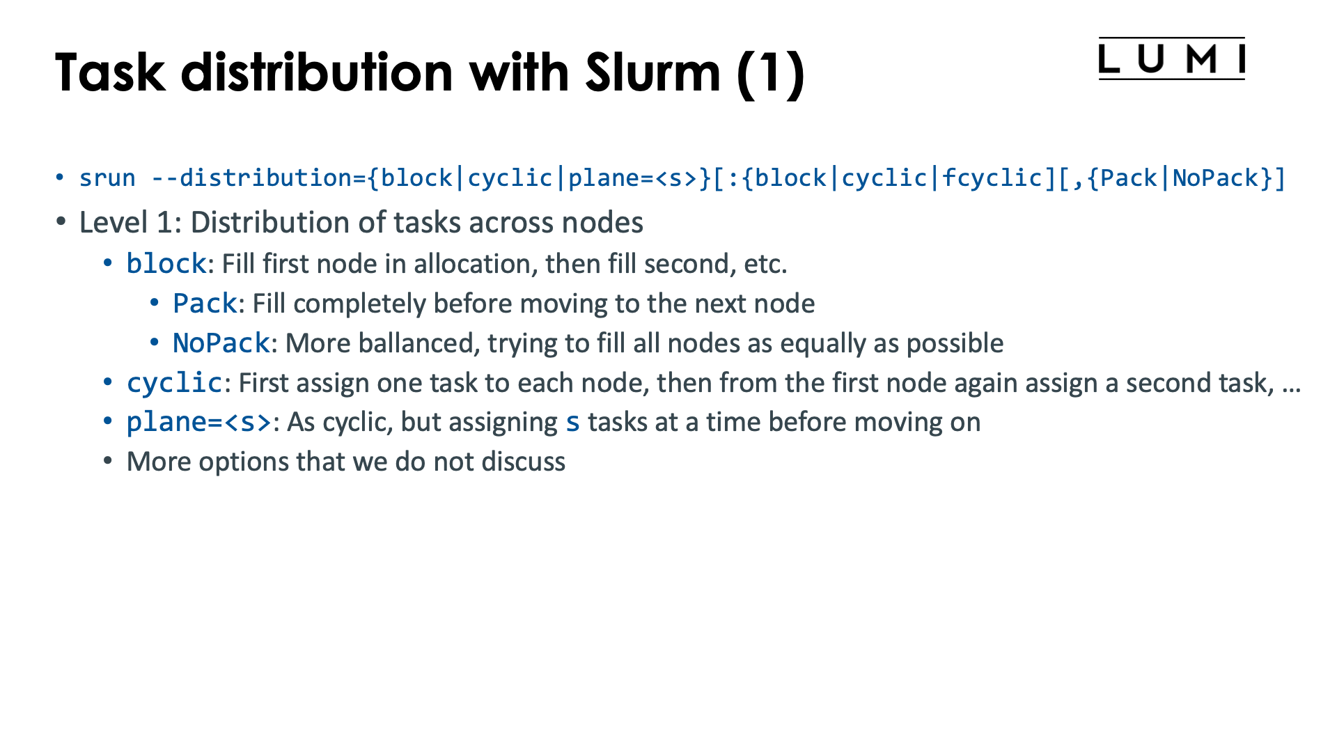
The Slurm srun command offers the --distribution option to influence the distribution of
tasks across nodes (level 1), sockets or NUMA domains (level 2 and sockets or NUMA) or
even across cores in the socket or NUMA domain (third level). The first level is the most useful level,
the second level is sometimes used but the third level is very tricky and both the second and third level
are often better replaced with other mechanisms that will also be discussed in this chapter on distribution
and binding.
The general form of the --distribution option is
--distribution={*|block|cyclic|arbitrary|plane=<size>}[:{*|block|cyclic|fcyclic}[:{*|block|cyclic|fcyclic}]][,{Pack|NoPack}]
-
Level 1: Distribution across nodes. There are three useful options for LUMI:
-
blockwhich is the default: A number of consecutive tasks is allocated on the first node, then another number of consecutive tasks on the second node, and so on till the last node of the allocation. Not all nodes may have the same number of tasks and this is determined by the optionalpackornopackparameter at the end.-
With
packthe first node in the allocation is first filled up as much as possible, then the second node, etc. -
With
nopacka more balanced approach is taken filling up all nodes as equally as possible. In fact, the number of tasks on each node will correspond to that of thecyclicdistribution, but the task numbers will be different.
-
-
cyclicassigns the tasks in a round-robin fashion to the nodes of the allocation. The first task is allocated to the first node, then the second one to the second node, and so on, and when all nodes of the allocation have received one task, the next one will be allocated again on the first node. -
plane=<size>is a combination of both of the former methods: Blocks of<size>consecutive tasks are allocated in a cyclic way.
-
-
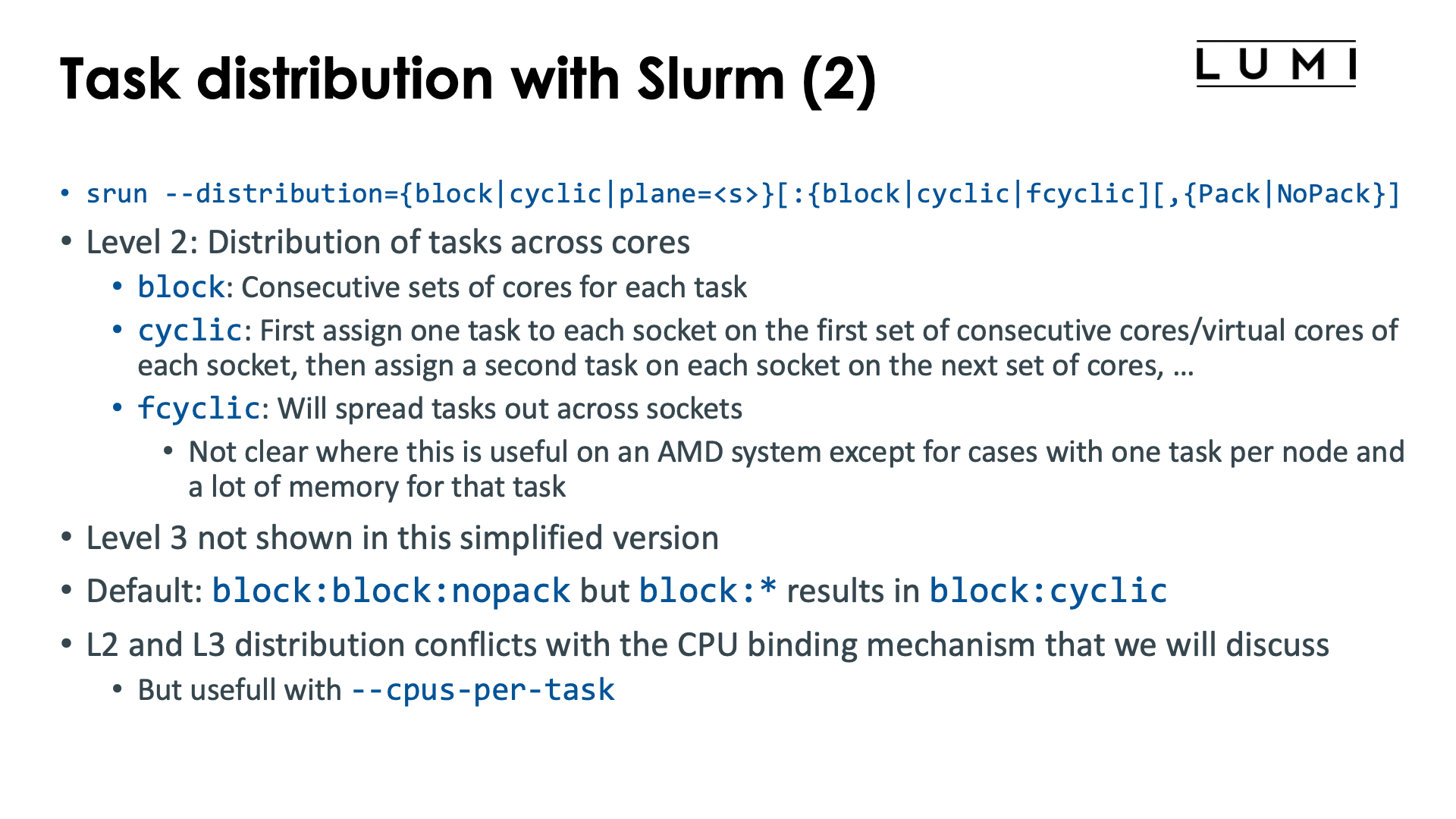
Level 2: Here we are distributing and pinning the tasks assigned to a node at level 1 across the sockets and cores of that node.
As this option already does a form of binding, it may conflict with other options that we will discuss later that also perform binding. In practice, this second level is less useful as often other mechanisms will be preferred for doing a proper binding, or the default behaviour is OK for simple distribution problems.
-
blockwill assign whole tasks to consecutive sets of cores on the node. On LUMI-C, it will first fill up the first socket before moving on to the second socket. -
cyclicassigns the first task of a node to a set of consecutive cores on the first socket, then the second task to a set of cores on the second socket, etc., in a round-robin way. It will do its best to not allocate tasks across sockets. -
fcyclicis a very strange distribution, where tasks requesting more than 1 CPU per task will see those spread out across sockets.We cannot see how this is useful on an AMD CPU except for cases where we have only one task per node which accesses a lot of memory (more than offered by a single socket) but does so in a very NUMA-aware way.
-
-
Level 3 is beyond the scope of an introductory course and rarely used.
The default behaviour of Slurm depends on LUMI seems to be block:block,nopack if --distribution is not specified,
though it is best to always verify as it can change over time and as the manual indicates that the
default differs according to the number of tasks compared to the number of nodes.
The defaults are also very tricky if a binding option at level 2 (or 3) is replaced with a * to mark
the default behaviour, e.g., --distribution="block:*" gives the result of --distribution=block:cyclic
while --distribution=block has the same effect as --distribution=block:block.
This option only makes sense on job-exclusive nodes.
Task-to-CPU binding with Slurm

The level 2 and 3 options from the previous section already do some binding. But we will now discuss a different option that enables very precise binding of tasks to hardware threads in Slurm.
The mechanism does conflict with some Slurm options that implicitly already do some binding, e.g.,
it will not always work together with --cpus-per-task and --hint=[no]multithread may also not
act as expected depending on how the options are used.
Level ⅔ control via --distribution sometimes also make no sense when this option is used
(and will be ignored).
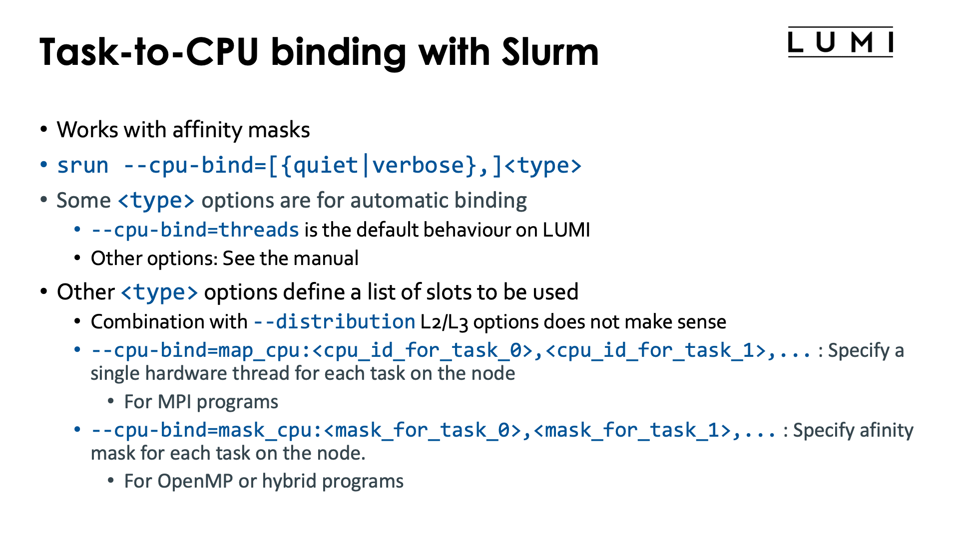
Task-to-CPU binding is controlled through the Slurm option
--cpu-bind=[{quiet|verbose},]<type>
We'll describe a few of the possibilities for the <type> parameter but for a more concrete overview
we refer to the Slurm srun manual page
-
--cpu-bind=threadsis the default behaviour on LUMI. -
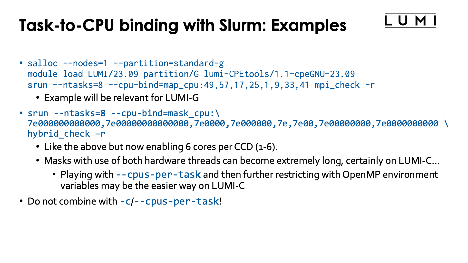
--cpu-bind=map_cpu:<cpu_id_for_task_0>,<cpu_id_for_task_1>, ...is used when tasks are bound to single cores. The first number is the number of the hardware thread for the task with local task ID 0, etc. In other words, this option at the same time also defines the slots that can be used by the--distributionoption above and replaces level 2 and level 3 of that option.E.g.,
salloc --nodes=1 --partition=standard-g
module load LUMI/23.09 partition/G lumi-CPEtools/1.1-cpeGNU-23.09
srun --ntasks=8 --cpu-bind=map_cpu:49,57,17,25,1,9,33,41 mpi_check -r
will run the first task on hardware threads 49, the second task on 57, third on 17, fourth on 25, fifth on 1, sixth on 9, seventh on 33 and eight on 41.
This may look like a very strange numbering, but we will see an application for it further in this chapter.
-
--cpu-bind=mask_cpu:<mask_for_task_0>,<mask_for_task_1>,...is similar tomap_cpu, but now multiple hardware threads can be specified per task through a mask. The mask is a hexadecimal number and leading zeros can be omitted. The least significant bit in the mask corresponds to HWT 0, etc.Masks can become very long, but we shall see that this option is very useful on the nodes of the
standard-gpartition. Just as withmap_cpu, this option replaces level 2 and 3 of the--distributionoption.E.g.,
salloc --nodes=1 --partition=standard-g
module load LUMI/23.09 partition/G lumi-CPEtools/1.1-cpeGNU-23.09
srun --ntasks=8 --cpu-bind=mask_cpu:7e000000000000,7e00000000000000,7e0000,7e000000,7e,7e00,7e00000000,7e0000000000 hybrid_check -r
will run the first task on hardware threads 49-54, the second task on 57-62, third on 17-22, fourth on 25-30, fifth on 1-6, sixth on 9-14, seventh on 33-38 and eight on 41-46.
The --cpu-bind=map_cpu and --cpu-bind=mask_gpu options also do not go together with -c / --cpus-per-task.
Both commands define a binding (the latter in combination with the default --gpu-bind=threads)
and these will usually conflict.
There are more options, but these are currently most relevant ones on LUMI. That may change in the future as LUMI User Support is investigating whether it isn't better to change the concept of "socket" in Slurm given how important it sometimes is to carefully map onto L3 cache domains for performance.
Task-to-GPU binding with Slurm
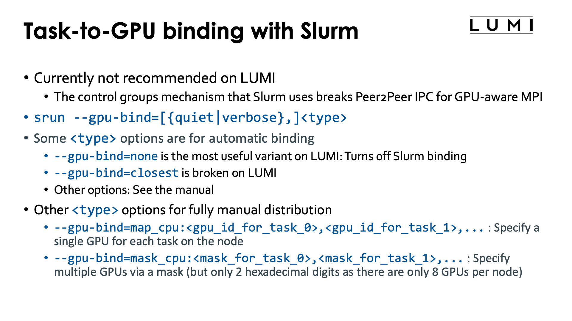
Doing the task-to-GPU binding fully via Slurm is currently not recommended on LUMI.
The problem is that Slurm uses control groups at the task level rather than just ROCR_VISIBLE_DEVICES
with the latter being more or less the equivalent of affinity masks. When using control groups this way,
the other GPUs in a job step on a node become completely invisible to a task, and the
Peer2Peer IPC mechanism for communication cannot be used anymore.
We present the options for completeness, and as it may still help users if the control group setup is not a problem for the application.
Task-to-GPU binding is done with
--gpu-bind=[verbose,]<type>
(see the Slurm manual)
which is somewhat similar to --cpu-binding (to the extent that that makes sense).
Some options for the <type> parameter that are worth considering:
-
--gpu-bind=closest: This currently does not work well on LUMI. The problem is being investigated so the situation may have changed by the time you read this. -
--gpu-bind=none: Turns off the GPU binding of Slurm. This can actually be useful on shared node jobs where doing a proper allocation of GPUs is difficult. You can then first use Slurm options such as--gpus-per-taskto get a working allocation of GPUs and CPUs, then un-bind and rebind using a different mechanism that we will discuss later. -
--gpu-bind=map_gpu:<list>is the equivalent of--cpu-bind=map_cpu:<list>. This option only makes sense on a job-exclusive node and is for jobs that need a single GPU per task. It defines the list of GPUs that should be used, with the task with local ID 0 using the first one in the list, etc. The numbering and topology was already discussed in the "LUMI ARchitecture" chapter, section "Building LUMI: What a LUMI-G really looks like. -
--gpu-bind=mask_gpu:<list>is the equivalent of--cpu-bind=mask_cpu:<list>. Now the bits in the mask correspond to individual GPUs, with GPU 0 the least significant bit. This option again only makes sense on a job-exclusive node.
Though map_gpu and mask_gpu could be very useful to get a proper mapping taking the topology of the
node into account, due to the current limitation of creating a control group per task it can not often
be used as it breaks some efficient communication mechanisms between tasks, including the GPU Peer2Peer
IPC used by Cray MPICH for intro-node MPI transfers if GPU aware MPI support is enabled.
What do the HPE Cray manuals say about this? (Click to expand)
From the HPE Cray CoE:
"Slurm may choose to use cgroups to implement the required
affinity settings. Typically, the use of cgroups has the downside of preventing the use of
GPU Peer2Peer IPC mechanisms. By default Cray MPI uses IPC for
implementing intra-node, inter-process MPI data movement operations that involve GPU-attached user buffers.
When Slurm’s cgroups settings are in effect, users are
advised to set MPICH_SMP_SINGLE_COPY_MODE=NONE or MPICH_GPU_IPC_ENABLED=0
to disable the use of IPC-based implementations.
Disabling IPC also has a noticeable impact on intra-node MPI performance when
GPU-attached memory regions are involved."
This is exactly what Slurm does on LUMI.
MPI rank redistribution with Cray MPICH

By default MPI rank i will use Slurm task i in a parallel job step.
With Cray MPICH this can be changed via the environment variable
MPICH_RANK_REORDER_METHOD. It provides an even more powerful way
of reordering MPI ranks than the Slurm --distribution option as one
can define fully custom orderings.
Rank reordering is an advanced topic that is discussed in more detail in the 4-day LUMI comprehensive courses organised by the LUMI User Support Team. The material of the latest one can be found via the course archive web page and is discussed in the "MPI Topics on the HPE Cray EX Supercomputer" which is often given on day 3.
Rank reordering can be used to reduce the number of inter-node messages or to spread those ranks that do parallel I/O over more nodes to increase the I/O bandwidth that can be obtained in the application.
Possible values for MPICH_RANK_REORDER_METHOD are:
-
export MPICH_RANK_REORDER_METHOD=0: Round-robin placement of the MPI ranks. This is the equivalent of the cyclic ordering in Slurm. -
export MPICH_RANK_REORDER_METHOD=1: This is the default and it preserves the ordering of Slurm, and the only one that makes sense with other L1 Slurm distributions thanblock.The Cray MPICH manual confusingly calls this "SMP-style ordering".
-
export MPICH_RANK_REORDER_METHOD=2: Folded rank placement. This is somewhat similar to round-robin, but when the last node is reached, the node list is transferred in the opposite direction. -
export MPICH_RANK_REORDER_METHOD=3: Use a custom ordering, given by theMPICH_RANK_ORDERfile which gives a comma-separated list of the MPI ranks in the order they should be assigned to slots on the nodes. The default filenameMPICH_RANK_ORDERcan be overwritten through the environment variableMPICH_RANK_REORDER_FILE.
Rank reordering does not always work well if Slurm is not using the (default) block ordering.
As the lumi-CPEtools mpi_check, hybrid_check and gpu_check commands use Cray MPICH
they can be used to test the Cray MPICH rank reordering also. The MPI ranks that are
displayed are the MPI ranks as seen through MPI calls and not the value of
SLURM_PROCID which is the Slurm task number.
The HPE Cray Programming Environment actually has profiling tools that help you determine the optimal rank ordering for a particular run, which is useful if you do a lot of runs with the same problem size (and hence same number of nodes and tasks).
Try the following job script (click to expand)
1 2 3 4 5 6 7 8 9 10 11 12 13 14 15 16 17 18 19 20 21 22 23 24 25 26 27 28 29 30 31 32 33 | |
Ths script starts 8 tasks that each take a quarter node.
-
The first
sruncommand (on line 15) is just the block distribution. The first 4 MPI ranks are on the first node, the next 4 on the second node.+ export MPICH_RANK_REORDER_METHOD=1 + MPICH_RANK_REORDER_METHOD=1 + srun -n 8 -c 32 -m block mpi_check -r Running 8 single-threaded MPI ranks. ++ mpi_check: MPI rank 0/8 on cpu 17/256 of nid001804 mask 0-31 ++ mpi_check: MPI rank 1/8 on cpu 32/256 of nid001804 mask 32-63 ++ mpi_check: MPI rank 2/8 on cpu 65/256 of nid001804 mask 64-95 ++ mpi_check: MPI rank 3/8 on cpu 111/256 of nid001804 mask 96-127 ++ mpi_check: MPI rank 4/8 on cpu 0/256 of nid001805 mask 0-31 ++ mpi_check: MPI rank 5/8 on cpu 32/256 of nid001805 mask 32-63 ++ mpi_check: MPI rank 6/8 on cpu 64/256 of nid001805 mask 64-95 ++ mpi_check: MPI rank 7/8 on cpu 120/256 of nid001805 mask 96-127 -
The second
sruncommand, on line 18, is an example where the Slurm cyclic distribution is preserved. MPI rank 0 now lands on the first 32 cores of node 0 of the allocation, MPI rank 1 on the first 32 cores of node 1 of the allocation, then task 2 on the second 32 cores of node 0, and so on:+ export MPICH_RANK_REORDER_METHOD=1 + MPICH_RANK_REORDER_METHOD=1 + srun -n 8 -c 32 -m cyclic mpi_check -r Running 8 single-threaded MPI ranks. ++ mpi_check: MPI rank 0/8 on cpu 0/256 of nid001804 mask 0-31 ++ mpi_check: MPI rank 1/8 on cpu 1/256 of nid001805 mask 0-31 ++ mpi_check: MPI rank 2/8 on cpu 32/256 of nid001804 mask 32-63 ++ mpi_check: MPI rank 3/8 on cpu 33/256 of nid001805 mask 32-63 ++ mpi_check: MPI rank 4/8 on cpu 79/256 of nid001804 mask 64-95 ++ mpi_check: MPI rank 5/8 on cpu 64/256 of nid001805 mask 64-95 ++ mpi_check: MPI rank 6/8 on cpu 112/256 of nid001804 mask 96-127 ++ mpi_check: MPI rank 7/8 on cpu 112/256 of nid001805 mask 96-127 -
The third
sruncommand, on line 21, uses Cray MPICH rank reordering instead to get a round-robin ordering rather than using the Slurm--distribution=cyclicoption. The result is the same as in the previous case:+ export MPICH_RANK_REORDER_METHOD=0 + MPICH_RANK_REORDER_METHOD=0 + srun -n 8 -c 32 -m block mpi_check -r Running 8 single-threaded MPI ranks. ++ mpi_check: MPI rank 0/8 on cpu 0/256 of nid001804 mask 0-31 ++ mpi_check: MPI rank 1/8 on cpu 1/256 of nid001805 mask 0-31 ++ mpi_check: MPI rank 2/8 on cpu 32/256 of nid001804 mask 32-63 ++ mpi_check: MPI rank 3/8 on cpu 47/256 of nid001805 mask 32-63 ++ mpi_check: MPI rank 4/8 on cpu 64/256 of nid001804 mask 64-95 ++ mpi_check: MPI rank 5/8 on cpu 64/256 of nid001805 mask 64-95 ++ mpi_check: MPI rank 6/8 on cpu 112/256 of nid001804 mask 96-127 ++ mpi_check: MPI rank 7/8 on cpu 112/256 of nid001805 mask 96-127 -
The fourth
sruncommand, on line 24, demonstrates the folded ordering: Rank 0 runs on the first 32 cores of node 0 of the allocation, rank 1 on the first 32 of node 1, then rank 2 runs on the second set of 32 cores again on node 1, with rank 3 then running on the second 32 cores of node 0, rank 4 on the third group of 32 cores of node 0, rank 5 on the third group of 32 cores on rank 1, and so on. So the nodes are filled in the order 0, 1, 1, 0, 0, 1, 1, 0.+ export MPICH_RANK_REORDER_METHOD=2 + MPICH_RANK_REORDER_METHOD=2 + srun -n 8 -c 32 -m block mpi_check -r Running 8 single-threaded MPI ranks. ++ mpi_check: MPI rank 0/8 on cpu 0/256 of nid001804 mask 0-31 ++ mpi_check: MPI rank 1/8 on cpu 17/256 of nid001805 mask 0-31 ++ mpi_check: MPI rank 2/8 on cpu 32/256 of nid001805 mask 32-63 ++ mpi_check: MPI rank 3/8 on cpu 32/256 of nid001804 mask 32-63 ++ mpi_check: MPI rank 4/8 on cpu 64/256 of nid001804 mask 64-95 ++ mpi_check: MPI rank 5/8 on cpu 64/256 of nid001805 mask 64-95 ++ mpi_check: MPI rank 6/8 on cpu 112/256 of nid001805 mask 96-127 ++ mpi_check: MPI rank 7/8 on cpu 112/256 of nid001804 mask 96-127 -
The fifth example ('srun' on line 31) demonstrate a custom reordering. Here we face a 4x2-grid which we want to split in 2 2x2 groups. So where the ranks in our grid are numbered as
0 1 2 3
4 5 6 7
we really want the left half of the grid on the first node of the allocation and the right half on the second node as this gives us less inter-node communication than when we would put the first line on the first node and the second line on the second. So basically we want ranks 0, 1, 4 and 5 on the first node and ranks 2, 3, 6 and 7 on the second node, which is done by creating the reorder file with content
0,1,4,5,2,3,6,7The resulting output is
+ export MPICH_RANK_REORDER_METHOD=3
+ MPICH_RANK_REORDER_METHOD=3
+ cat
+ srun -n 8 -c 32 -m block mpi_check -r

Running 8 single-threaded MPI ranks.

++ mpi_check: MPI rank   0/8   on cpu   0/256 of nid001804 mask 0-31
++ mpi_check: MPI rank   1/8   on cpu  32/256 of nid001804 mask 32-63
++ mpi_check: MPI rank   2/8   on cpu   1/256 of nid001805 mask 0-31
++ mpi_check: MPI rank   3/8   on cpu  32/256 of nid001805 mask 32-63
++ mpi_check: MPI rank   4/8   on cpu  64/256 of nid001804 mask 64-95
++ mpi_check: MPI rank   5/8   on cpu 112/256 of nid001804 mask 96-127
++ mpi_check: MPI rank   6/8   on cpu  64/256 of nid001805 mask 64-95
++ mpi_check: MPI rank   7/8   on cpu 112/256 of nid001805 mask 96-127
Refining core binding in OpenMP applications


In a Slurm batch job step, threads of a shared memory process will be contained to all
hardware threads of all available cores on the first node of your allocation. To contain
a shared memory program to the hardware threads asked for in the allocation (i.e., to ensure
that --hint=[no]multithread has effect) you'd have to start the shared memory program with
srun in a regular job step.
Any multithreaded executable run as a shared memory job or ranks in a hybrid MPI/multithread job,
will - when started properly via srun - get access to a group of cores via an affinity mask.
In some cases you will want to manually refine the way individual threads of each process are
mapped onto the available hardware threads.
In OpenMP, this is usually done through environment variables (it can also be done partially in the program through library calls). A number of environment variables is standardised in the OpenMP standard, but some implementations offer some additional non-standard ones, or non-standard values for the standard environment variables. Below we discuss the more important of the standard ones:
-
OMP_NUM_THREADSis used to set the number of CPU threads OpenMP will use. In its most basic form this is a single number (but you can give multiple comma-separated numbers for nested parallelism).OpenMP programs on LUMI will usually correctly detect how many hardware threads are available to the task and use one OpenMP thread per hardware thread. There are cases where you may want to ask for a certain number of hardware threads when allocating resources, e.g., to easily get a good mapping of tasks on cores, but do not want to use them all, e.g., because your application is too memory bandwidth or cache constrained and using fewer threads actually gives better overall performance on a per-node basis.
-
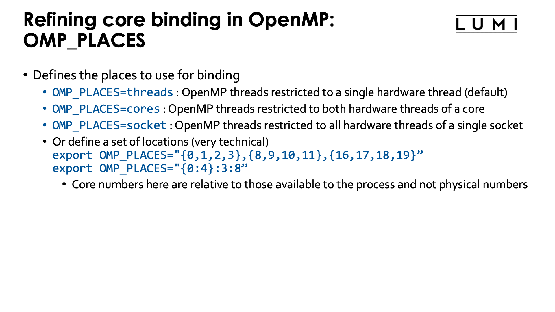
OMP_PLACESis used to restrict each OpenMP thread to a group of hardware threads. Possible values include:OMP_PLACES=threadsto restrict OpenMP threads to a single hardware threadOMP_PLACES=coresto restrict each OpenMP threads to a single core (but all hardware threads associated with that core)OMP_PLACES=socketsto restrict each OpenMP thread to the hardware threads of a single socket-
And it is possible to give a list with explicit values, e.g.,
export OMP_PLACES="{0:4}:3:8"which is also equivalent to
export OMP_PLACES="{0,1,2,3},{8,9,10,11},{16,17,18,19}"so each OpenMP thread is restricted to a different group of 4 hardware threads. The numbers in the list are not the physical Linux hardware thread numbers, but are relative to the hardware threads available in the affinity mask of the task.
More general,
{a:b}:c:dmeans b numbers starting from a (so a, a+1, ..., a+b-1), repeated c times, at every repeat shifted by d. There are more variants to generate lists of places and we show another one in the example below. But in all the syntax may look strange and there are manuals that give the wrong information (including some versions of the manual for the GNU OpenMP runtime).Note that this is different from the core numbers that would be used in
--cpu-bind=map_cpuor--gpu-bind=mask_cpuwhich sets the CPUs or groups of CPUs available to each thread and which always use the physical numbering and not a numbering that is local to the job allocation.
-
OMP_PROC_BIND: Sets how threads are distributed over the places. Possible values are:-
OMP_PROC_BIND=false: Turn off OpenMP thread binding. Each thread will get access to all hardware threads available in to the task (and defined by a Linux affinity mask in Slurm). -
OMP_PROC_BIND=close: If more places are available than there are OpenMP threads, then try to put the OpenMP threads in different places as close as possible to the master thread. In general, bind as close as possible to the master thread while still distributing for load balancing. -
OMP_PROC_BIND=spread: Spread threads out as evenly as possible over the places available to the task. -
OMP_PROC_BIND=master: Bind threads to the same place as the master thread. The place is determined by theOMP_PLACESenvironment variable and it is clear this makes no sense if that place is just a single hardware thread or single core as all threads would then be competing for the resources of a single core.
Multiple values of
close,spreadandmasterin a comma-separated list are possible to organise nested OpenMP parallelism, but this is outside of the scope of this tutorial.The Cray Compilation Environment also has an additional non-standard option
autowhich is actually the default and tries to do a reasonable job for most cases. On the other compilers on LUMI, the default behaviour isfalseunless the next environment variable,OMP_PLACES, is specified. -
-
OMP_DISPLAY_AFFINITY: When set totTRUEinformation about the affinity binding of each thread will be shown which is good for debugging purposes.
For single-level OpenMP parallelism, the omp_check and hybrid_check programs from the lumi-CPEtools modules
can also be used to check the OpenMP thread binding.
Some examples (click to expand)
Consider the following job script:
#!/bin/bash
#SBATCH --account=project_46YXXXXXX
#SBATCH --job-name=omp-demo
#SBATCH --output %x-%j.txt
#SBATCH --partition=standard
#SBATCH --nodes=1
#SBATCH --hint=multithread
#SBATCH --time=5:00

module load LUMI/23.09 partition/C lumi-CPEtools/1.1-cpeCray-23.09

set -x
export OMP_NUM_THREADS=4
export OMP_PROC_BIND=false
srun -n 1 -c 32 --hint=multithread   omp_check -r
srun -n 1 -c 16 --hint=nomultithread omp_check -r

export OMP_NUM_THREADS=4
unset OMP_PROC_BIND
srun -n 1 -c 32 --hint=multithread   omp_check -r
srun -n 1 -c 16 --hint=nomultithread omp_check -r

export OMP_NUM_THREADS=4
export OMP_PROC_BIND=close
srun -n 1 -c 32 --hint=multithread   omp_check -r
srun -n 1 -c 16 --hint=nomultithread omp_check -r

export OMP_NUM_THREADS=4
export OMP_PROC_BIND=spread
srun -n 1 -c 32 --hint=multithread   omp_check -r
srun -n 1 -c 16 --hint=nomultithread omp_check -r

export OMP_NUM_THREADS=4
export OMP_PROC_BIND=close
export OMP_PLACES=threads
srun -n 1 -c 32 --hint=multithread   omp_check -r
export OMP_PLACES=cores
srun -n 1 -c 32 --hint=multithread   omp_check -r

export OMP_NUM_THREADS=4
export OMP_PROC_BIND=close
export OMP_PLACES="{0:8}:4:8"
srun -n 1 -c 32 --hint=multithread   omp_check -r

export OMP_PLACES="{0:4,16:4}:4:4"
srun -n 1 -c 32 --hint=multithread   omp_check -r
set +x
Let's check the output step by step:
In the first block we run 2 srun commands that actually both use 16 cores, but first with
hardware threading enabled in Slurm and then with multithread mode off in Slurm:
+ export OMP_NUM_THREADS=4
+ OMP_NUM_THREADS=4
+ export OMP_PROC_BIND=false
+ OMP_PROC_BIND=false
+ srun -n 1 -c 32 --hint=multithread omp_check -r

Running 4 threads in a single process

++ omp_check: OpenMP thread   0/4   on cpu   0/256 of nid001077 mask 0-15, 128-143
++ omp_check: OpenMP thread   1/4   on cpu 137/256 of nid001077 mask 0-15, 128-143
++ omp_check: OpenMP thread   2/4   on cpu 129/256 of nid001077 mask 0-15, 128-143
++ omp_check: OpenMP thread   3/4   on cpu 143/256 of nid001077 mask 0-15, 128-143

+ srun -n 1 -c 16 --hint=nomultithread omp_check -r

Running 4 threads in a single process

++ omp_check: OpenMP thread   0/4   on cpu   0/256 of nid001077 mask 0-15
++ omp_check: OpenMP thread   1/4   on cpu  15/256 of nid001077 mask 0-15
++ omp_check: OpenMP thread   2/4   on cpu   1/256 of nid001077 mask 0-15
++ omp_check: OpenMP thread   3/4   on cpu  14/256 of nid001077 mask 0-15
OMP_PROC_BIND was explicitly set to false to disable the Cray Compilation Environment default behaviour.
The masks reported by omp_check cover all hardware threads available to the task in Slurm: Both hardware
threads for the 16 first cores in the multithread case and just the primary hardware thread on the first 16 cores
in the second case. So each OpenMP thread can in principle migrate over all available hardware threads.
In the second block we unset the PROC_BIND environment variable to demonstrate the behaviour of the
Cray Compilation Environment. The output would be different had we used the cpeGNU or cpeAOCC version.
+ export OMP_NUM_THREADS=4
+ OMP_NUM_THREADS=4
+ unset OMP_PROC_BIND
+ srun -n 1 -c 32 --hint=multithread omp_check -r

Running 4 threads in a single process

++ omp_check: OpenMP thread   0/4   on cpu   1/256 of nid001077 mask 0-3, 128-131
++ omp_check: OpenMP thread   1/4   on cpu   4/256 of nid001077 mask 4-7, 132-135
++ omp_check: OpenMP thread   2/4   on cpu   8/256 of nid001077 mask 8-11, 136-139
++ omp_check: OpenMP thread   3/4   on cpu 142/256 of nid001077 mask 12-15, 140-143

+ srun -n 1 -c 16 --hint=nomultithread omp_check -r

Running 4 threads in a single process

++ omp_check: OpenMP thread   0/4   on cpu   0/256 of nid001077 mask 0-3
++ omp_check: OpenMP thread   1/4   on cpu   4/256 of nid001077 mask 4-7
++ omp_check: OpenMP thread   2/4   on cpu   9/256 of nid001077 mask 8-11
++ omp_check: OpenMP thread   3/4   on cpu  15/256 of nid001077 mask 12-15
The default behaviour of the CCE is very nice: Threads are nicely spread out over the available cores and then all get access to their own group of hardware threads that in this case with 4 threads for 16 cores spans 4 cores for each thread. In fact, also in other cases the default behaviour of CCE will be a binding that works well for many cases.
In the next experiment we demonstrate the close binding:
+ export OMP_NUM_THREADS=4
+ OMP_NUM_THREADS=4
+ export OMP_PROC_BIND=close
+ OMP_PROC_BIND=close
+ srun -n 1 -c 32 --hint=multithread omp_check -r

Running 4 threads in a single process

++ omp_check: OpenMP thread   0/4   on cpu   0/256 of nid001077 mask 0
++ omp_check: OpenMP thread   1/4   on cpu 128/256 of nid001077 mask 128
++ omp_check: OpenMP thread   2/4   on cpu   1/256 of nid001077 mask 1
++ omp_check: OpenMP thread   3/4   on cpu 129/256 of nid001077 mask 129

+ srun -n 1 -c 16 --hint=nomultithread omp_check -r

Running 4 threads in a single process

++ omp_check: OpenMP thread   0/4   on cpu   0/256 of nid001077 mask 0
++ omp_check: OpenMP thread   1/4   on cpu   1/256 of nid001077 mask 1
++ omp_check: OpenMP thread   2/4   on cpu   2/256 of nid001077 mask 2
++ omp_check: OpenMP thread   3/4   on cpu   3/256 of nid001077 mask 3
In the first case, with Slurm multithreading mode on, we see that the 4 threads are now concentrated on only 2 cores but each gets pinned to its own hardware thread. In general this behaviour is not what one wants if more cores are available as on each core two threads will now be competing for available resources. In the second case, with Slurm multithreading disabled, the threads are bound to the first 4 cores, with one core for each thread.
Next we demonstrate the spread binding:
+ export OMP_NUM_THREADS=4
+ OMP_NUM_THREADS=4
+ export OMP_PROC_BIND=spread
+ OMP_PROC_BIND=spread
+ srun -n 1 -c 32 --hint=multithread omp_check -r

Running 4 threads in a single process

++ omp_check: OpenMP thread   0/4   on cpu   0/256 of nid001077 mask 0
++ omp_check: OpenMP thread   1/4   on cpu   4/256 of nid001077 mask 4
++ omp_check: OpenMP thread   2/4   on cpu   8/256 of nid001077 mask 8
++ omp_check: OpenMP thread   3/4   on cpu  12/256 of nid001077 mask 12

+ srun -n 1 -c 16 --hint=nomultithread omp_check -r

Running 4 threads in a single process

++ omp_check: OpenMP thread   0/4   on cpu   0/256 of nid001077 mask 0
++ omp_check: OpenMP thread   1/4   on cpu   4/256 of nid001077 mask 4
++ omp_check: OpenMP thread   2/4   on cpu   8/256 of nid001077 mask 8
++ omp_check: OpenMP thread   3/4   on cpu  12/256 of nid001077 mask 12
The result is now the same in both cases as we have fewer threads than physical cores. Each OpenMP thread is bound to a single core, but these cores are spread out over the first 16 cores of the node.
Next we return to the close binding but try both threads and cores as places
with Slurm multithreading turned on for both cases:
+ export OMP_NUM_THREADS=4
+ OMP_NUM_THREADS=4
+ export OMP_PROC_BIND=close
+ OMP_PROC_BIND=close
+ export OMP_PLACES=threads
+ OMP_PLACES=threads
+ srun -n 1 -c 32 --hint=multithread omp_check -r

Running 4 threads in a single process

++ omp_check: OpenMP thread   0/4   on cpu   0/256 of nid001077 mask 0
++ omp_check: OpenMP thread   1/4   on cpu 128/256 of nid001077 mask 128
++ omp_check: OpenMP thread   2/4   on cpu   1/256 of nid001077 mask 1
++ omp_check: OpenMP thread   3/4   on cpu 129/256 of nid001077 mask 129

+ export OMP_PLACES=cores
+ OMP_PLACES=cores
+ srun -n 1 -c 32 --hint=multithread omp_check -r

Running 4 threads in a single process

++ omp_check: OpenMP thread   0/4   on cpu   0/256 of nid001077 mask 0, 128
++ omp_check: OpenMP thread   1/4   on cpu   1/256 of nid001077 mask 1, 129
++ omp_check: OpenMP thread   2/4   on cpu 130/256 of nid001077 mask 2, 130
++ omp_check: OpenMP thread   3/4   on cpu   3/256 of nid001077 mask 3, 131
With threads as places we get again the distribution with two OpenMP threads on each
physical core, each with their own hardware thread. With cores as places, we get only one
thread per physical core, but each thread has access to both hardware threads of that physical core.
And lastly we play a bit with custom placements:
+ export OMP_NUM_THREADS=4
+ OMP_NUM_THREADS=4
+ export OMP_PROC_BIND=close
+ OMP_PROC_BIND=close
+ export 'OMP_PLACES={0:8}:4:8'
+ OMP_PLACES='{0:8}:4:8'
+ srun -n 1 -c 32 --hint=multithread omp_check -r

Running 4 threads in a single process

++ omp_check: OpenMP thread   0/4   on cpu   0/256 of nid001077 mask 0-7
++ omp_check: OpenMP thread   1/4   on cpu   8/256 of nid001077 mask 8-15
++ omp_check: OpenMP thread   2/4   on cpu 128/256 of nid001077 mask 128-135
++ omp_check: OpenMP thread   3/4   on cpu 136/256 of nid001077 mask 136-143
OMP_PLACES='{0:8}:4:8 means: Take starting from core with logical number 0 8 cores and
repeat this 4 times, shifting by 8 each time, so effectively
OMP_PLACES="{ 0,1,2,3,4,5,6,7},{8,9,10,11,12,13,14,15},{16,17,18,19,20,21,22,23},{24,25,26,27,27,28,30,31}"
omp_check however shows the OS numbering for the hardware threads so we can see what this places variable means:
the first thread can get scheduled on the first hardware thread of the first 8 cores, the second thread on the first
hardware thread of the next 8 cores, the third OpenMP thread on the second thread of the first 8 cores, and the
fourth OpenMP thread on the second hardware thread of the next 8 cores. In other words, the logical numbering of the
threads follows the same ordering as at the OS level: First the first hardware thread of each core, then the second
hardware thread.
When trying another variant with
OMP_PACES={0:4,16:4}:4:4
which is equivalent to
OMP_PLACES={0,1,2,3,16,17,18,19},{4,5,6,7,20,21,22,23},{8,9,10,11,24,25,26,27},{12,13,14,15,28,29,30,31}"
we get a much nicer distribution:
+ export 'OMP_PLACES={0:4,16:4}:4:4'
+ OMP_PLACES='{0:4,16:4}:4:4'
+ srun -n 1 -c 32 --hint=multithread omp_check -r

Running 4 threads in a single process

++ omp_check: OpenMP thread   0/4   on cpu   0/256 of nid001077 mask 0-3, 128-131
++ omp_check: OpenMP thread   1/4   on cpu 132/256 of nid001077 mask 4-7, 132-135
++ omp_check: OpenMP thread   2/4   on cpu 136/256 of nid001077 mask 8-11, 136-139
++ omp_check: OpenMP thread   3/4   on cpu 140/256 of nid001077 mask 12-15, 140-143
We only discussed a subset of the environment variables defined in the OpenMP standard. Several implementations
also offer additional environment variables, e.g.,
a number of GOMP_* environment variables in the GNU Compiler Collection implementation or KMP_* variables in the Intel compiler (not available on LUMI).
Some further documentation:
-
The
OMP_*environment variables and a number of environment variables specific for the runtime libraries of the Cray Compiling Environment are discussed in theintro_openmpmanual page, section "Environment variables". -
A list of OMP_ environment variables in the OpenMP 5.1 standard (as the current list in the HTML version of the 5.2 standard has some problems).
GPU binding with ROCR_VISIBLE_DEVICES

The ROCR_VISIBLE_DEVICES environment variable restricts access to GPUs at the ROCm platform runtime
level. Contrary to control groups however this mechanism is compatible with the Peer2Peer IPC used by
GPU-aware Cray MPI for intra-node communication.
The value of the ROCR_VISIBLE_DEVICES environment variable is a list of device indices that will be
exposed to the applications. The device indices do depend on the control group. Visible devices in a control
group are always numbered from 0.
So though ROCR_VISIBLE_DEVICES has the same function as affinity masks for CPUs, it is different in
many respects.
-
Affinity masks are part of the Linux kernel and fully OS-controlled, while
ROCR_VISIBLE_DEVICESis interpreted in the ROCmTM stack. -
Affinity masks are set through an OS call and that call can enforce that the new mask cannot be less restrictive than the parent mask.
ROCR_VISIBLE_DEVICESis just an environment variable, so at the time that you try to set it to a value that you shouldn't use, there is no check. -
Affinity masks always use the global numbering of hardware threads while
ROCR_VISIBLE_DEVICESuses the local numbering in the currently active control group. So the GPU that corresponds to 0 inROCR_VISIBLE_DEVICESis not always the same GPU.
Alternative values for ROCR_VISIBLE_DEVICES
Instead of device indices, ROCR_VISIBLE_DEVICES also accepts GPU UUIDs that are unique to each
GPU. This is less practical then it seems as the UUIDs of GPUs are different on each node so one
would need to discover them first before they can be used.
Combining Slurm task binding with ROCR_VISIBLE_DEVICES
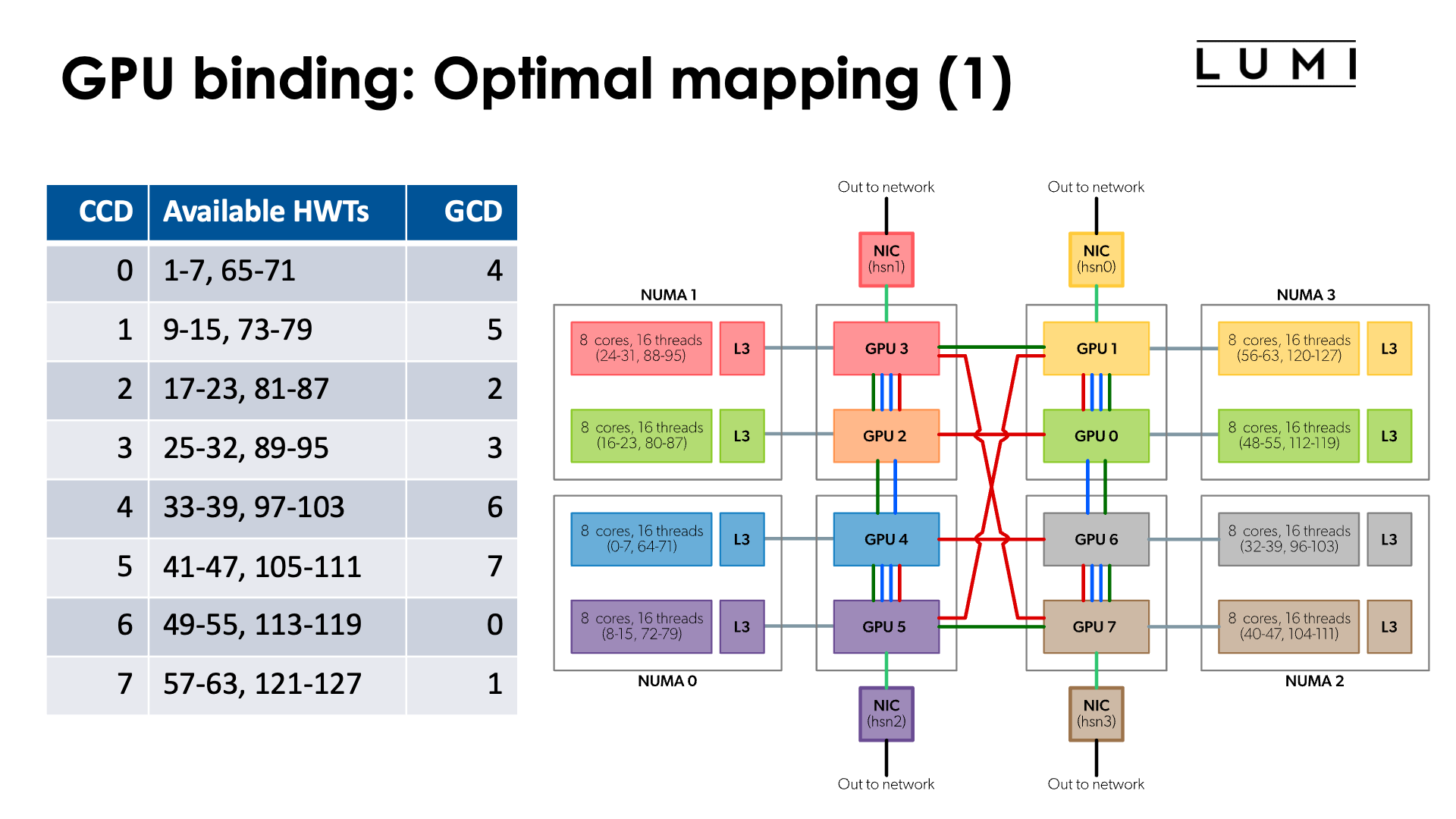
In the chapter on the architecture of LUMI we discussed what a LUMI-G really looks like.
The full topology of a LUMI-G compute node is shown in the figure:

Note that the numbering of GCDs does not correspond to the numbering of CCDs/cores. However, for optimal memory transfers (and certainly if cache-coherent memory access from CPU to GPU would be used) it is better to ensure that each GCD collaborates with the matched CCD in an MPI rank. So we have the mapping:
| CCD | HWTs | Available HWTs | GCD |
|---|---|---|---|
| 0 | 0-7, 64-71 | 1-7, 65-71 | 4 |
| 1 | 8-15, 72-79 | 9-15, 73-79 | 5 |
| 2 | 16-23, 80-87 | 17-23, 81-87 | 2 |
| 3 | 24-32, 88-95 | 25-32, 89-95 | 3 |
| 4 | 32-39, 96-103 | 33-39, 97-103 | 6 |
| 5 | 40-47, 104-111 | 41-47, 105-111 | 7 |
| 6 | 48-55, 112-119 | 49-55, 113-119 | 0 |
| 7 | 56-63, 120-127 | 57-63, 121-127 | 1 |
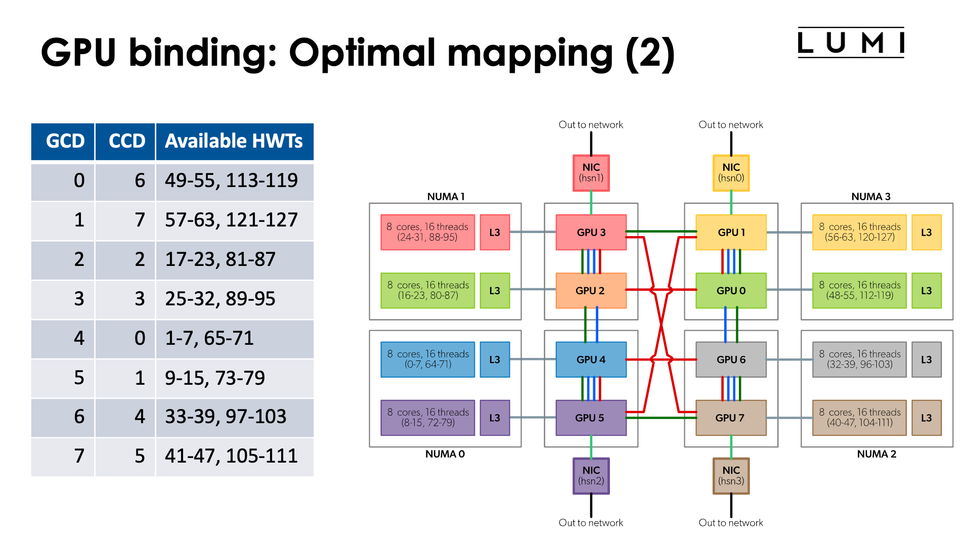
or the reverse mapping
| GCD | CCD | HWTs | Available HWTs |
|---|---|---|---|
| 0 | 6 | 48-55, 112-119 | 49-55, 113-119 |
| 1 | 7 | 56-63, 120-127 | 57-63, 121-127 |
| 2 | 2 | 16-23, 80-87 | 17-23, 81-87 |
| 3 | 3 | 24-32, 88-95 | 25-32, 89-95 |
| 4 | 0 | 0-7, 64-71 | 1-7, 65-71 |
| 5 | 1 | 8-15, 72-79 | 9-15, 73-79 |
| 6 | 4 | 32-39, 96-103 | 33-39, 97-103 |
| 7 | 5 | 40-47, 104-111 | 41-47, 105-111 |

Moreover, if you look more carefully at the topology, you can see that the connections between the GCDs contain a number of rings:
-
Green ring: 0 - 1 - 3 - 2 - 4 - 5 - 7 - 6 - 0
-
Red ring: 0 - 1 - 5 - 4 - 6 - 7 - 3 - 2 - 0
-
Sharing some connections with the previous ones, but can be combined with the green ring: 0 - 1 - 5 - 4 - 2 - 3 - 7 - 6 - 0
So if your application would use a ring mapping for communication and use communication from GPU buffers for that, than it may be advantageous to map the MPI ranks on one of those rings which would mean that neither the order of the CCDs nor the order of the GCDs is trivial.
Some other topologies can also be mapped on these connections (but unfortunately not a 3D cube).
Note: The red ring and green ring correspond to the red and green rings on page 6 of the "Introducing AMD CDNATM 2 Architecture" whitepaper.
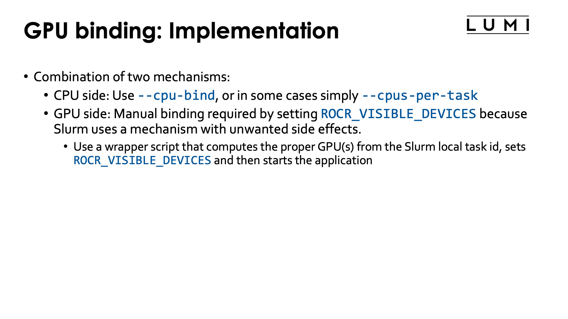
To implement a proper CCD-to-GCD mapping we will use two mechanisms:
-
On the CPU side we'll use Slurm
--cpu-bind. Sometimes we can also simply use-cor--cpus-per-task(in particular in the case below with linear ordering of the CCDs and 7 cores per task) -
On the GPU side we will manually assign GPUs via a different value of
ROCR_VISIBLE_DEVICESfor each thread. To accomplish this we will have to write a wrapper script which we will generate in the job script.
Let us start with the simplest case:
Linear assignment of GCD, then match the cores
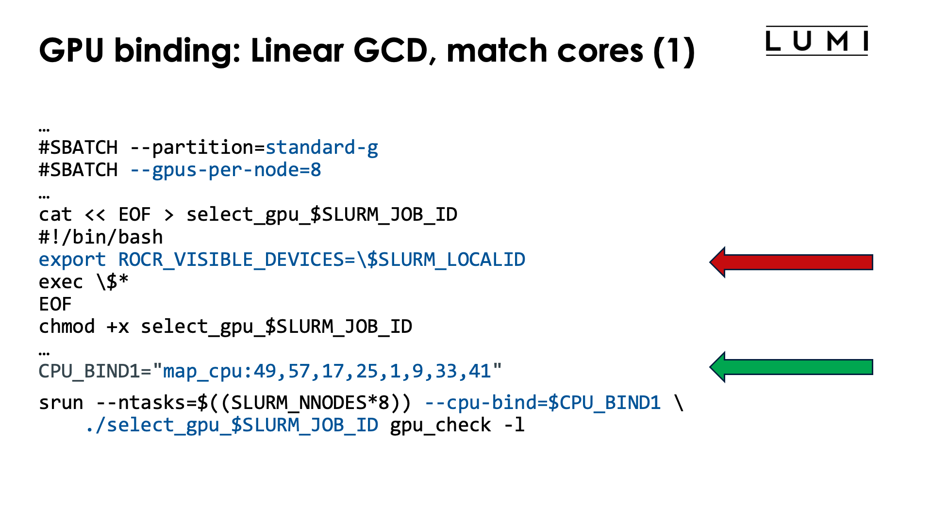
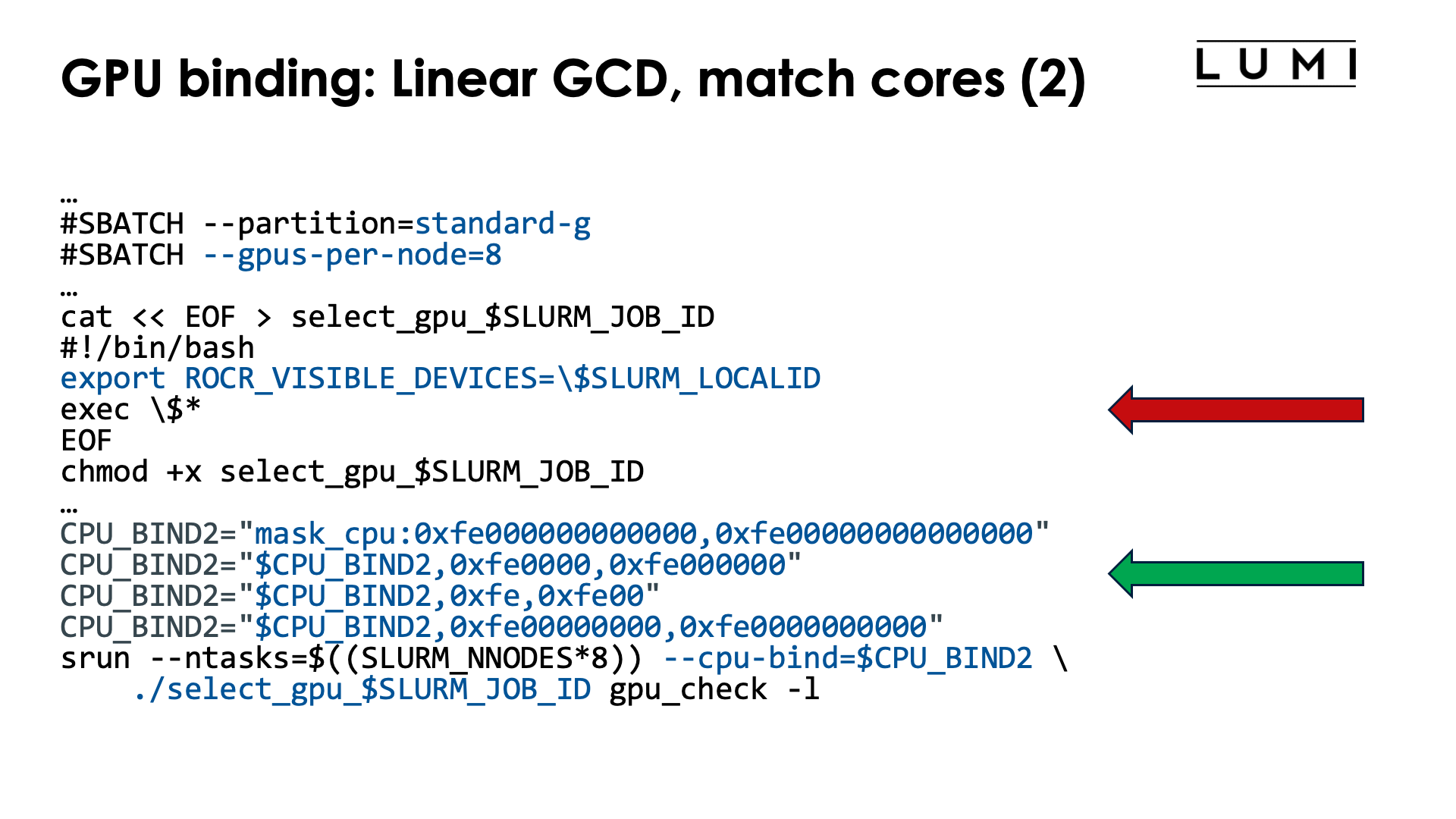
One possible job script to accomplish this is:
#!/bin/bash
#SBATCH --account=project_46YXXXXXX
#SBATCH --job-name=map-linear-GCD
#SBATCH --output %x-%j.txt
#SBATCH --partition=standard-g
#SBATCH --gpus-per-node=8
#SBATCH --nodes=1
#SBATCH --time=5:00

module load LUMI/23.09 partition/G lumi-CPEtools/1.1-cpeCray-23.09

cat << EOF > select_gpu_$SLURM_JOB_ID
#!/bin/bash
export ROCR_VISIBLE_DEVICES=\$SLURM_LOCALID
exec \$*
EOF
chmod +x select_gpu_$SLURM_JOB_ID

CPU_BIND1="map_cpu:49,57,17,25,1,9,33,41"

CPU_BIND2="mask_cpu:0xfe000000000000,0xfe00000000000000"
CPU_BIND2="$CPU_BIND2,0xfe0000,0xfe000000"
CPU_BIND2="$CPU_BIND2,0xfe,0xfe00"
CPU_BIND2="$CPU_BIND2,0xfe00000000,0xfe0000000000"

export MPICH_GPU_SUPPORT_ENABLED=0

echo -e "\nPure MPI:\n"
srun --ntasks=$((SLURM_NNODES*8)) --cpu-bind=$CPU_BIND1 ./select_gpu_$SLURM_JOB_ID mpi_check -r
srun --ntasks=$((SLURM_NNODES*8)) --cpu-bind=$CPU_BIND1 ./select_gpu_$SLURM_JOB_ID gpu_check -l

echo -e "\nHybrid:\n"
srun --ntasks=$((SLURM_NNODES*8)) --cpu-bind=$CPU_BIND2 ./select_gpu_$SLURM_JOB_ID hybrid_check -r
srun --ntasks=$((SLURM_NNODES*8)) --cpu-bind=$CPU_BIND2 ./select_gpu_$SLURM_JOB_ID gpu_check -l

/bin/rm -f select_gpu_$SLURM_JOB_ID
To select the GPUs we either use a map with numbers of cores (ideal for pure MPI programs)
or masks (the only option for hybrid programs). The mask that we give in the example uses
7 cores per CCD and always skips the first core, as is required on LUMI as
the first core of each chiplet
is reserved and not available to Slurm jobs. To select the right GPU for ROCR_VISIBLE_DEVICES
we can use the Slurm local task ID which is
also what the MPI rank will be.
We use a so-called "bash here document"
to generate the script. Note that in the bash here document
we needed to protect the $ with a backslash (so use \$) as otherwise the variables would
already be expanded when generating the script file.
Instead of the somewhat complicated --ntasks with srun we could have specified --ntasks-per-node=8
on a #SBATCH line which would have fixed the structure for all srun commands. Even though we want
to use all GPUs in the node, --gpus-per-node or an equivalent option has to be specified either
as an #SBATCH line or with each srun command or no GPUs will be made available to the tasks
started by the srun command.
Note the output of the second srun command:
MPI 000 - OMP 000 - HWT 049 (CCD6) - Node nid006872 - RT_GPU_ID 0 - GPU_ID 0 - Bus_ID c1(GCD0/CCD6)
MPI 001 - OMP 000 - HWT 057 (CCD7) - Node nid006872 - RT_GPU_ID 0 - GPU_ID 1 - Bus_ID c6(GCD1/CCD7)
MPI 002 - OMP 000 - HWT 017 (CCD2) - Node nid006872 - RT_GPU_ID 0 - GPU_ID 2 - Bus_ID c9(GCD2/CCD2)
MPI 003 - OMP 000 - HWT 025 (CCD3) - Node nid006872 - RT_GPU_ID 0 - GPU_ID 3 - Bus_ID cc(GCD3/CCD3)
MPI 004 - OMP 000 - HWT 001 (CCD0) - Node nid006872 - RT_GPU_ID 0 - GPU_ID 4 - Bus_ID d1(GCD4/CCD0)
MPI 005 - OMP 000 - HWT 009 (CCD1) - Node nid006872 - RT_GPU_ID 0 - GPU_ID 5 - Bus_ID d6(GCD5/CCD1)
MPI 006 - OMP 000 - HWT 033 (CCD4) - Node nid006872 - RT_GPU_ID 0 - GPU_ID 6 - Bus_ID d9(GCD6/CCD4)
MPI 007 - OMP 000 - HWT 041 (CCD5) - Node nid006872 - RT_GPU_ID 0 - GPU_ID 7 - Bus_ID dc(GCD7/CCD5)
With the -l option we also print some information about the CCD that a core belongs to and the
GCD and corresponding optimal CCD for each PCIe bus ID, which makes it very easy to check if the
mapping is as intended. Note that the GCDs are indeed in the linear order starting with GCD0.
Linear assignment of the CCDs, then match the GCD
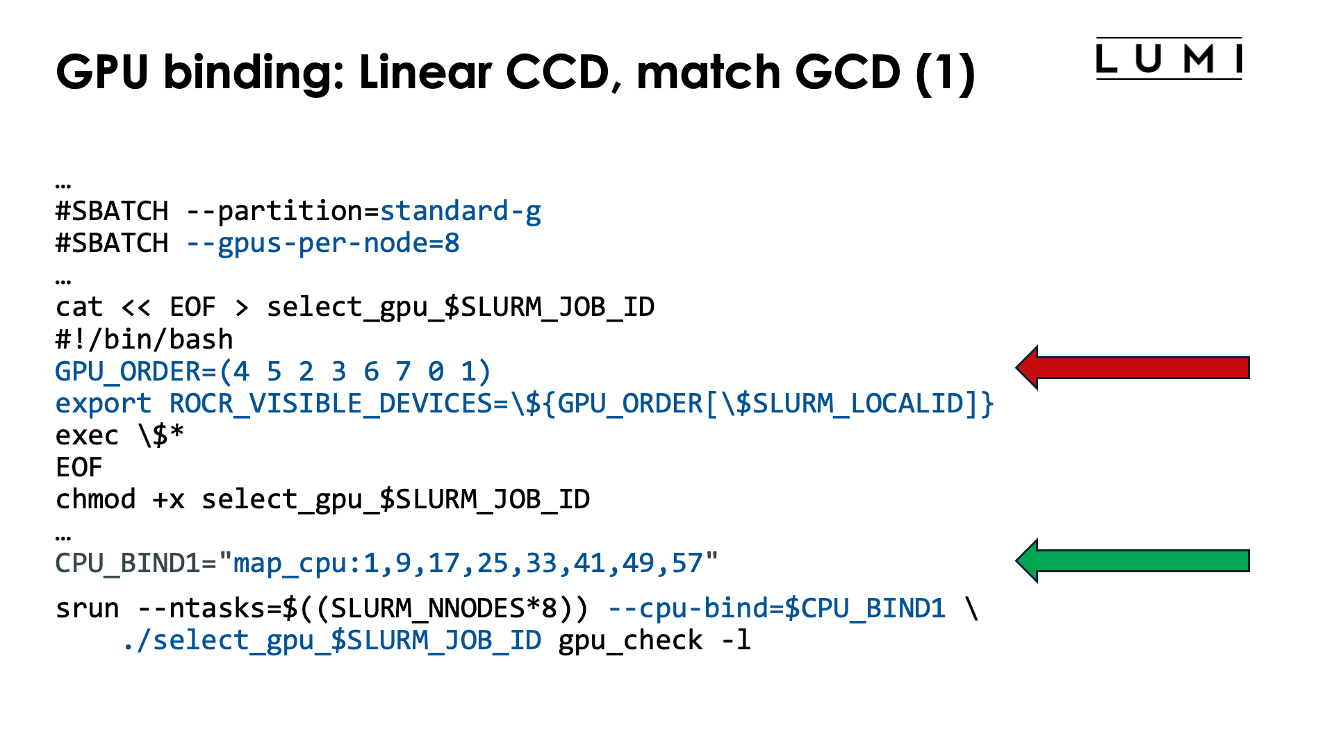
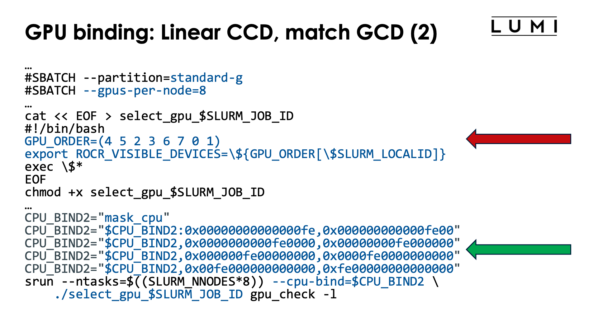
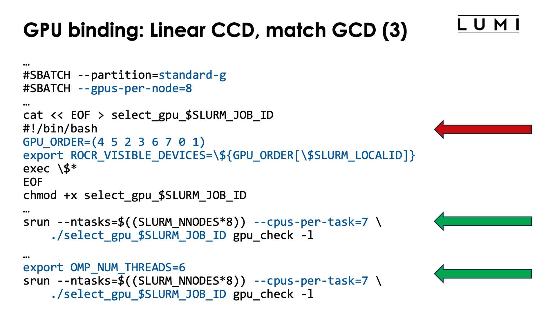
To modify the order of the GPUs, we now use an array with the desired order in the select_gpu script.
With the current setup of LUMI, with one core reserved on each chiplet, there are now two options
to get the proper CPUs:
-
We can use masks to define the cores for each slot, but they will now look more regular, or
-
we can simply use
--cpus-per-task=7and then further restrict the number of threads per task withOMP_NUM_THREADS.
The job script (for option 1) now becomes:
#!/bin/bash
#SBATCH --account=project_46YXXXXXX
#SBATCH --job-name=map-linear-CCD
#SBATCH --output %x-%j.txt
#SBATCH --partition=standard-g
#SBATCH --gpus-per-node=8
#SBATCH --nodes=1
#SBATCH --time=5:00

module load LUMI/22.12 partition/G lumi-CPEtools/1.1-cpeCray-22.12

cat << EOF > select_gpu_$SLURM_JOB_ID
#!/bin/bash
GPU_ORDER=(4 5 2 3 6 7 0 1)
export ROCR_VISIBLE_DEVICES=\${GPU_ORDER[\$SLURM_LOCALID]}
exec \$*
EOF
chmod +x select_gpu_$SLURM_JOB_ID

CPU_BIND1="map_cpu:1,9,17,25,33,41,49,57"

CPU_BIND2="mask_cpu"
CPU_BIND2="$CPU_BIND2:0x00000000000000fe,0x000000000000fe00"
CPU_BIND2="$CPU_BIND2,0x0000000000fe0000,0x00000000fe000000"
CPU_BIND2="$CPU_BIND2,0x000000fe00000000,0x0000fe0000000000"
CPU_BIND2="$CPU_BIND2,0x00fe000000000000,0xfe00000000000000"

export MPICH_GPU_SUPPORT_ENABLED=0

echo -e "\nPure MPI:\n"
srun --ntasks=$((SLURM_NNODES*8)) --cpu-bind=$CPU_BIND1 ./select_gpu_$SLURM_JOB_ID mpi_check -r
srun --ntasks=$((SLURM_NNODES*8)) --cpu-bind=$CPU_BIND1 ./select_gpu_$SLURM_JOB_ID gpu_check -l

echo -e "\nHybrid:\n"
srun --ntasks=$((SLURM_NNODES*8)) --cpu-bind=$CPU_BIND2 ./select_gpu_$SLURM_JOB_ID hybrid_check -r
srun --ntasks=$((SLURM_NNODES*8)) --cpu-bind=$CPU_BIND2 ./select_gpu_$SLURM_JOB_ID gpu_check -l

/bin/rm -f select_gpu_$SLURM_JOB_ID
The leading zeros in the masks in the CPU_BIND2 environment variable are not needed but we added
them as it makes it easier to see which chiplet is used in what position.
The green ring
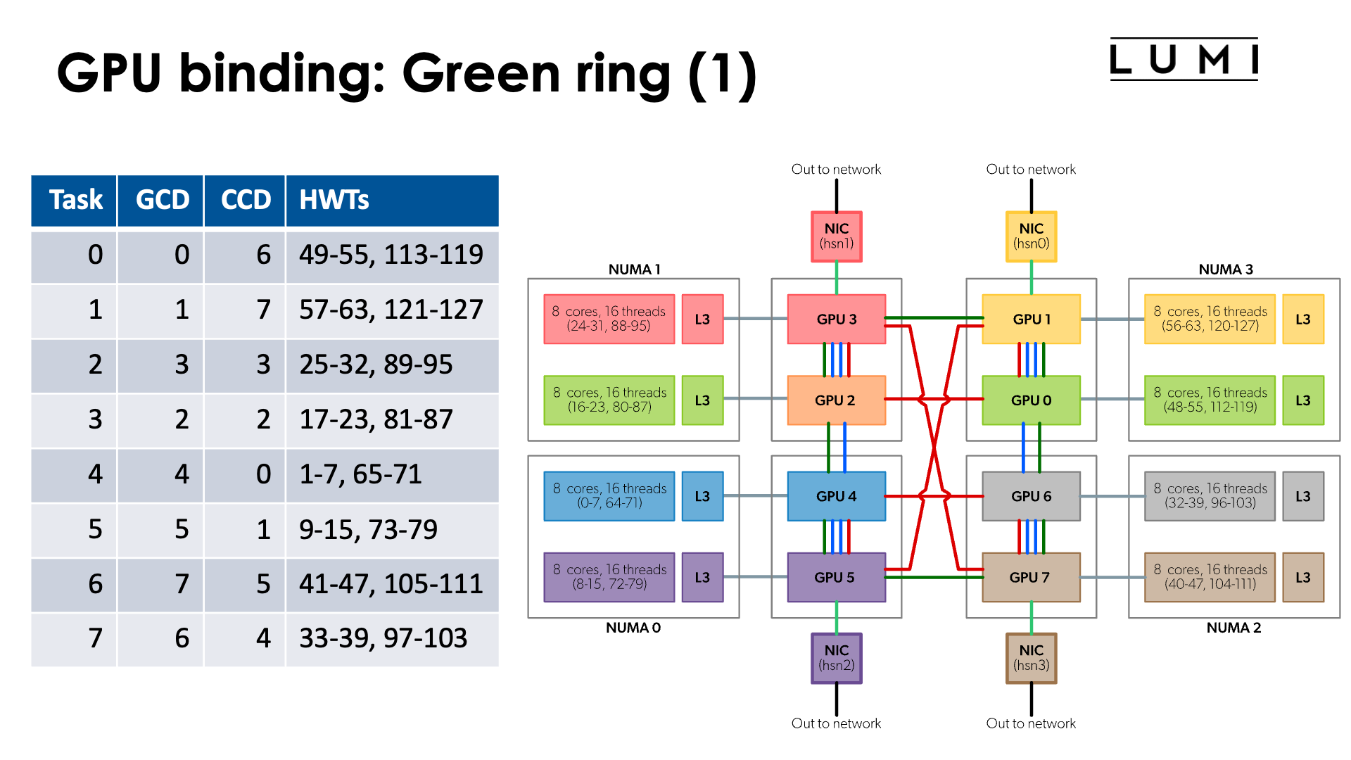
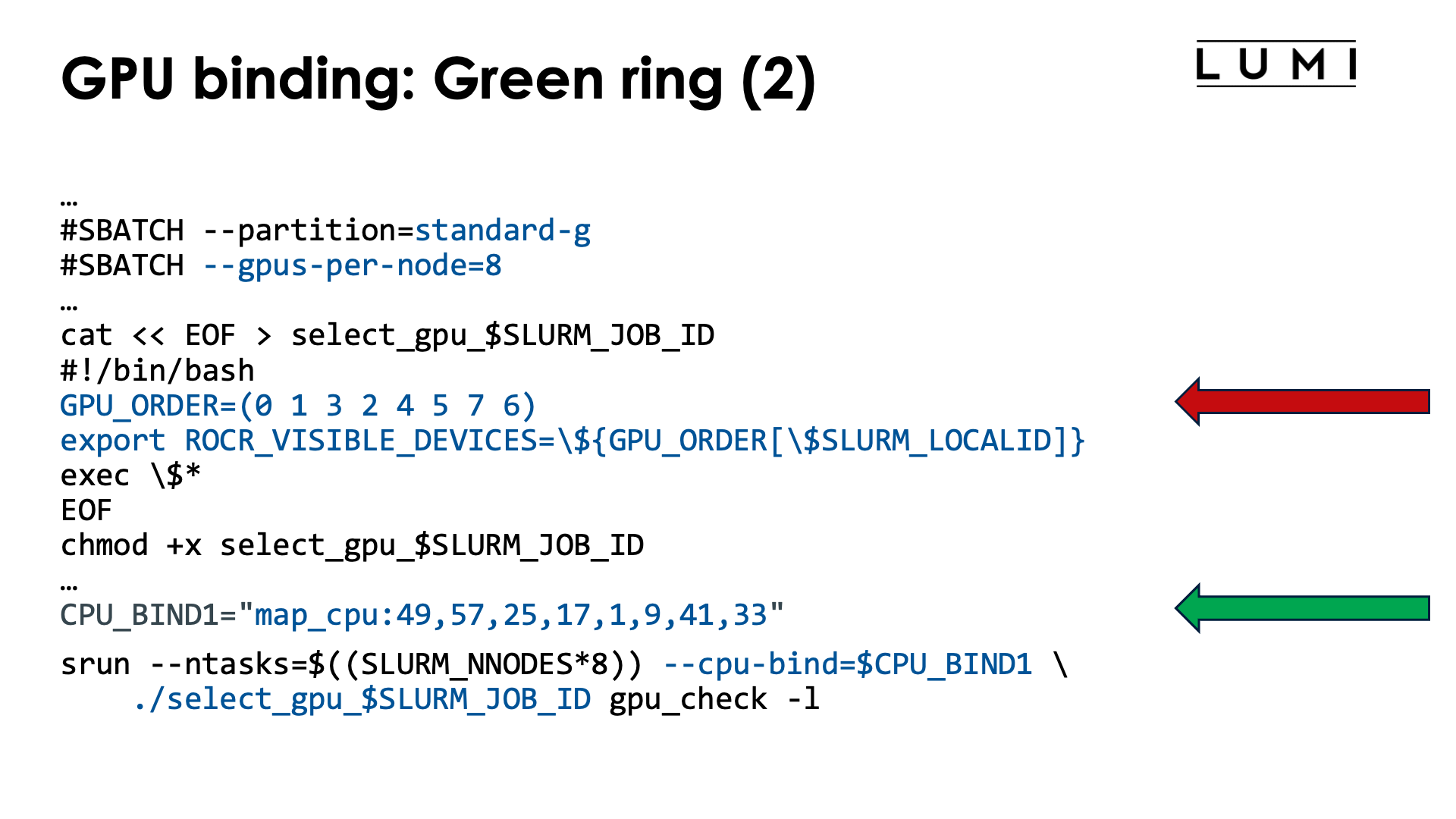
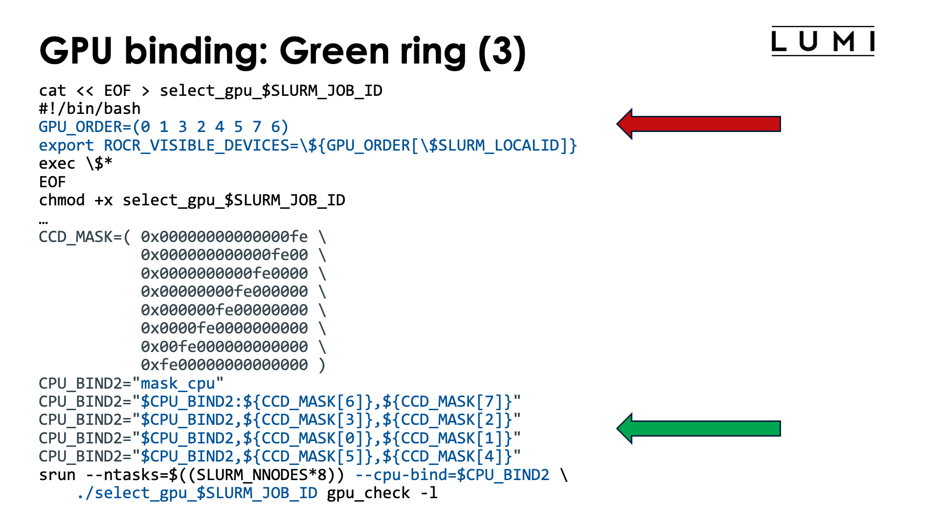
As a final example for whole node allocations, lets bind tasks such that the MPI ranks are mapped upon the green ring which is GCD 0 - 1 - 3 - 2 - 4 - 5 - 7 - 6 - 0. In other words, we want to create the mapping
| Task | GCD | CCD | Available cores |
|---|---|---|---|
| 0 | 0 | 6 | 49-55, 113-119 |
| 1 | 1 | 7 | 57-63, 121-127 |
| 2 | 3 | 3 | 25-32, 89-95 |
| 3 | 2 | 2 | 17-23, 81-87 |
| 4 | 4 | 0 | 1-7, 65-71 |
| 5 | 5 | 1 | 9-15, 73-79 |
| 6 | 7 | 5 | 41-47, 105-111 |
| 7 | 6 | 4 | 33-39, 97-103 |
This mapping would be useful when using GPU-to-GPU communication in a scenario where task i only communicates with tasks i-1 and i+1 (module 8), so the communication pattern is a ring.
Now we need to reorder both the cores and the GCDs, so we basically combine the approach taken in the two scripts above:
#!/bin/bash
#SBATCH --account=project_46YXXXXXX
#SBATCH --job-name=map-ring-green
#SBATCH --output %x-%j.txt
#SBATCH --partition=standard-g
#SBATCH --gpus-per-node=8
#SBATCH --nodes=1
#SBATCH --time=5:00

module load LUMI/23.09 partition/G lumi-CPEtools/1.1-cpeCray-23.09

# Mapping:
# | Task | GCD | CCD | Available cores |
# |-----:|----:|----:|:----------------|
# |    0 |   0 |   6 | 49-55, 113-119  |
# |    1 |   1 |   7 | 57-63, 121-127  |
# |    2 |   3 |   3 | 25-32, 89-95    |
# |    3 |   2 |   2 | 17-23, 81-87    |
# |    4 |   4 |   0 | 1-7, 65-71      |
# |    5 |   5 |   1 | 9-15, 73-79     |
# |    6 |   7 |   5 | 41-47, 105-111  |
# |    7 |   6 |   4 | 33-39, 97-103   |

cat << EOF > select_gpu_$SLURM_JOB_ID
#!/bin/bash
GPU_ORDER=(0 1 3 2 4 5 7 6)
export ROCR_VISIBLE_DEVICES=\${GPU_ORDER[\$SLURM_LOCALID]}
exec \$*
EOF
chmod +x select_gpu_$SLURM_JOB_ID

CPU_BIND1="map_cpu:49,57,25,17,1,9,41,33"

CCD_MASK=( 0x00000000000000fe \
           0x000000000000fe00 \
           0x0000000000fe0000 \
           0x00000000fe000000 \
           0x000000fe00000000 \
           0x0000fe0000000000 \
           0x00fe000000000000 \
           0xfe00000000000000 )
CPU_BIND2="mask_cpu"
CPU_BIND2="$CPU_BIND2:${CCD_MASK[6]},${CCD_MASK[7]}"
CPU_BIND2="$CPU_BIND2,${CCD_MASK[3]},${CCD_MASK[2]}"
CPU_BIND2="$CPU_BIND2,${CCD_MASK[0]},${CCD_MASK[1]}"
CPU_BIND2="$CPU_BIND2,${CCD_MASK[5]},${CCD_MASK[4]}"

export MPICH_GPU_SUPPORT_ENABLED=0

echo -e "\nPure MPI:\n"
srun --ntasks=$((SLURM_NNODES*8)) --cpu-bind=$CPU_BIND1 ./select_gpu_$SLURM_JOB_ID mpi_check -r
srun --ntasks=$((SLURM_NNODES*8)) --cpu-bind=$CPU_BIND1 ./select_gpu_$SLURM_JOB_ID gpu_check -l

echo -e "\nHybrid:\n"
srun --ntasks=$((SLURM_NNODES*8)) --cpu-bind=$CPU_BIND2 ./select_gpu_$SLURM_JOB_ID hybrid_check -r
srun --ntasks=$((SLURM_NNODES*8)) --cpu-bind=$CPU_BIND2 ./select_gpu_$SLURM_JOB_ID gpu_check -l

/bin/rm -f select_gpu_$SLURM_JOB_ID
The values for GPU_ORDER are easily read from the second column of the table with the mapping
that we prepared. The cores to use for the pure MPI run are also easily read from the table:
simply take the first core of each line. Finally, to build the mask,
we used some bash trickery. We first define the bash array CCD_MASK with the mask for each chiplet.
As this has a regular structure, this is easy to build. Then we compose the mask list for the CPUs
by indexing in that array, where the indices are easily read from the third column in the mapping.
The alternative code to build CPU_BIND2 is
CPU_BIND2="mask_cpu"
CPU_BIND2="$CPU_BIND2:0x00fe000000000000,0xfe00000000000000"
CPU_BIND2="$CPU_BIND2,0x00000000fe000000,0x0000000000fe0000"
CPU_BIND2="$CPU_BIND2,0x00000000000000fe,0x000000000000fe00"
CPU_BIND2="$CPU_BIND2,0x0000fe0000000000,0x000000fe00000000"
which may be shorter, but requires some puzzling to build and hence is more prone to error.
The output of the second srun command is now
MPI 000 - OMP 000 - HWT 049 (CCD6) - Node nid005083 - RT_GPU_ID 0 - GPU_ID 0 - Bus_ID c1(GCD0/CCD6)
MPI 001 - OMP 000 - HWT 057 (CCD7) - Node nid005083 - RT_GPU_ID 0 - GPU_ID 1 - Bus_ID c6(GCD1/CCD7)
MPI 002 - OMP 000 - HWT 025 (CCD3) - Node nid005083 - RT_GPU_ID 0 - GPU_ID 3 - Bus_ID cc(GCD3/CCD3)
MPI 003 - OMP 000 - HWT 017 (CCD2) - Node nid005083 - RT_GPU_ID 0 - GPU_ID 2 - Bus_ID c9(GCD2/CCD2)
MPI 004 - OMP 000 - HWT 001 (CCD0) - Node nid005083 - RT_GPU_ID 0 - GPU_ID 4 - Bus_ID d1(GCD4/CCD0)
MPI 005 - OMP 000 - HWT 009 (CCD1) - Node nid005083 - RT_GPU_ID 0 - GPU_ID 5 - Bus_ID d6(GCD5/CCD1)
MPI 006 - OMP 000 - HWT 041 (CCD5) - Node nid005083 - RT_GPU_ID 0 - GPU_ID 7 - Bus_ID dc(GCD7/CCD5)
MPI 007 - OMP 000 - HWT 033 (CCD4) - Node nid005083 - RT_GPU_ID 0 - GPU_ID 6 - Bus_ID d9(GCD6/CCD4)
Checking the last column, we see that the GCDs are indeed in the desired order for the green ring, and is is also easy to check that each task is also mapped on the optimal CCD for the GCD.
Job script with some more advanced bash
#!/bin/bash
#SBATCH --job-name=map-advanced-multiple
#SBATCH --output %x-%j.txt
#SBATCH --partition=standard-g
#SBATCH --gpus-per-node=8
#SBATCH --nodes=1
#SBATCH --time=5:00

module load LUMI/23.09 partition/G lumi-CPEtools/1.1-cpeCray-23.09

#
# Define the order of the GPUs and the core mask for CCD0
# It is important that the order of the GPUs is a string with the numbers separated by spaces.
#
GCD_ORDER="0 1 5 4 6 7 3 2"
coremask='2#00000010'  # Can use the binary representation, hexadecimal with 0x, or decimal

#
# run_gpu script, takes the string with GCDs as the first argument.
#
cat << EOF > run_gpu_$SLURM_JOB_ID
#!/bin/bash
GCD_ORDER=( \$1 )
shift
export ROCR_VISIBLE_DEVICES=\${GCD_ORDER[\$SLURM_LOCALID]}
exec "\$@"
EOF
chmod +x run_gpu_$SLURM_JOB_ID

#
# Build the CPU binding
# Argument one is mask, all other arguments are treated as an array of GCD numbers.
#

function generate_mask {

    # First argument is the mask for CCD0
    mask=$1

    # Other arguments are either a string already with the GCDs, or just one GCD per argument.
    shift
    GCDs=( "$@" )
    # Fully expand (doesn't matter as the loop can deal with it, but good if we want to check the number)
    GCDs=( ${GCDs[@]} )

    # For each GCD, the corresponding CCD number in the optimal mapping.
    MAP_to_CCD=( 6 7 2 3 0 1 4 5 )

    CPU_BIND=""

    # Loop over the GCDs in the order of the list to compute the corresponding
    # CPU mask.
    for GCD in ${GCDs[@]}
    do
        # Get the matching CCD for this GCD
        CCD=${MAP_to_CCD[$GCD]}

        # Shift the mask for CCD0 to the position for CCD $CCD
        printf -v tmpvar "0x%016x" $((mask << $((CCD*8))))

        # Add to CPU_BIND. We'll remove the leading , this creates later.
        CPU_BIND="$CPU_BIND,$tmpvar"
    done

    # Strip the leading ,
    CPU_BIND="${CPU_BIND#,}"

    # Return the result by printing to stdout
    printf "$CPU_BIND"

}

#
# Running the check programs
#

export MPICH_GPU_SUPPORT_ENABLED=1

# Some mappings:
linear_CCD="4 5 2 3 6 7 0 1"
linear_GCD="0 1 2 3 4 5 6 7"
ring_green="0 1 3 2 4 5 7 6"
ring_red="0 1 5 4 6 7 3 2"

echo -e "\nTest runs:\n"

echo -e "\nConsecutive CCDs:\n"
srun --ntasks=$((SLURM_NNODES*8)) \
     --cpu-bind=mask_cpu:$(generate_mask $coremask $linear_CCD) \
     ./run_gpu_$SLURM_JOB_ID "$linear_CCD" gpu_check -l

echo -e "\nConsecutive GCDs:\n"
srun --ntasks=$((SLURM_NNODES*8)) \
     --cpu-bind=mask_cpu:$(generate_mask $coremask $linear_GCD) \
     ./run_gpu_$SLURM_JOB_ID "$linear_GCD" gpu_check -l

echo -e "\nGreen ring:\n"
srun --ntasks=$((SLURM_NNODES*8)) \
     --cpu-bind=mask_cpu:$(generate_mask $coremask $ring_green) \
     ./run_gpu_$SLURM_JOB_ID "$ring_green" gpu_check -l

echo -e "\nRed ring:\n"
srun --ntasks=$((SLURM_NNODES*8)) \
     --cpu-bind=mask_cpu:$(generate_mask $coremask $ring_red) \
     ./run_gpu_$SLURM_JOB_ID "$ring_red" gpu_check -l

echo -e "\nFirst two CPU NUMA domains (assuming one node in the allocation):"
half="4 5 2 3"
srun --ntasks=4 \
     --cpu-bind=mask_cpu:$(generate_mask $coremask $half) \
     ./run_gpu_$SLURM_JOB_ID "$half" gpu_check -l

/bin/rm -f run_gpu_$SLURM_JOB_ID
In this script, we have modified the and renamed the usual select_gpu script (renamed to run_cpu) to take
as the first argument a string with a space-separated list of the GCDs to use. This has
been combined with the bash function generate_mask (which could have been transformed in a script as well)
that computes the CPU mask starting from the mask for CCD0 and shifting that mask as needed.
The input is the mask to use and then the GCDs to use, either as a single string or as a
series of arguments (e.g., resulting from an array expansion).
Both commands are then combined in the srun command. The generate_mask function is used to generate
the mask for --gpu-bind while the run_gpu script is used to set ROCR_VISIBLE_DEVICES for each task.
The examples also show how easy it is to experiment with different mappings. The one limitation of the
script and function is that there can be only 1 GPU per task and one task per GPU, and the CPU mask is also
limited to a single CCD (which makes sense with the GPU restriction). Generating masks that also include the
second hardware thread is not supported yet. (We use bash arithmetic internally which is limited to 64-bit integers).
What about "allocate by resources" partitions?

On partitions that are "allocatable by resource", e.g., small-g, you are never guaranteed that tasks
will be spread in a reasonable way over the CCDs and that the matching GPUs will be available to your job.
Creating an optimal mapping or taking the topology into account is hence impossible.
What is possible though is work around the fact that with the usual options for such resource allocations,
Slurm will lock up the GPUs for individual tasks in control groups so that the Peer2Peer IPC intra-node
communication mechanism has to be turned off. We can do this for job steps that follow the pattern of
resources allocated via the sbatch arguments (usually #SBATCH lines), and rely on three elements for that:
-
We can turn off the Slurm GPU binding mechanism with
--gpu-bind=none. -
Even then, the GPUs will still be locked up in a control group on each node for the job and hence on each node be numbered starting from zero.
-
And each task also has a local ID that can be used to map the appropriate number of GPUs to each task.
This can be demonstrated with the following job script:
#! /bin/bash
#SBATCH --account=project_46YXXXXXX
#SBATCH --job-name=map-smallg-1gpt
#SBATCH --output %x-%j.txt
#SBATCH --partition=small-g
#SBATCH --ntasks=12
#SBATCH --cpus-per-task=2
#SBATCH --gpus-per-task=1
#SBATCH --hint=nomultithread
#SBATCH --time=5:00

module load LUMI/23.09 partition/G lumi-CPEtools/1.1-cpeCray-23.09

cat << EOF > select_gpu_$SLURM_JOB_ID
#!/bin/bash
export ROCR_VISIBLE_DEVICES=\$SLURM_LOCALID
exec \$*
EOF
chmod +x ./select_gpu_$SLURM_JOB_ID

cat << EOF > echo_dev_$SLURM_JOB_ID
#!/bin/bash
printf -v task "%02d" \$SLURM_PROCID
echo "Task \$task or node.local_id \$SLURM_NODEID.\$SLURM_LOCALID sees ROCR_VISIBLE_DEVICES=\$ROCR_VISIBLE_DEVICES"
EOF
chmod +x ./echo_dev_$SLURM_JOB_ID

set -x
srun gpu_check -l
srun ./echo_dev_$SLURM_JOB_ID | sort
srun --gpu-bind=none ./echo_dev_$SLURM_JOB_ID | sort
srun --gpu-bind=none ./select_gpu_$SLURM_JOB_ID ./echo_dev_$SLURM_JOB_ID | sort
srun --gpu-bind=none ./select_gpu_$SLURM_JOB_ID gpu_check -l
set +x

/bin/rm -f select_gpu_$SLURM_JOB_ID echo_dev_$SLURM_JOB_ID
To run this job successfully, we need 12 GPUs so obviously the tasks will be spread over more than
one node. The echo_dev command in this script only shows us the value of ROCR_VISIBLE_DEVICES
for the task at that point, something that gpu_check in fact also reports as GPU_ID, but this
is just in case you don't believe...
The output of the first srun command is:
+ srun gpu_check -l
MPI 000 - OMP 000 - HWT 001 (CCD0) - Node nid007379 - RT_GPU_ID 0 - GPU_ID 0 - Bus_ID c1(GCD0/CCD6)
MPI 000 - OMP 001 - HWT 002 (CCD0) - Node nid007379 - RT_GPU_ID 0 - GPU_ID 0 - Bus_ID c1(GCD0/CCD6)
MPI 001 - OMP 000 - HWT 003 (CCD0) - Node nid007379 - RT_GPU_ID 0 - GPU_ID 0 - Bus_ID c6(GCD1/CCD7)
MPI 001 - OMP 001 - HWT 004 (CCD0) - Node nid007379 - RT_GPU_ID 0 - GPU_ID 0 - Bus_ID c6(GCD1/CCD7)
MPI 002 - OMP 000 - HWT 005 (CCD0) - Node nid007379 - RT_GPU_ID 0 - GPU_ID 0 - Bus_ID c9(GCD2/CCD2)
MPI 002 - OMP 001 - HWT 006 (CCD0) - Node nid007379 - RT_GPU_ID 0 - GPU_ID 0 - Bus_ID c9(GCD2/CCD2)
MPI 003 - OMP 000 - HWT 007 (CCD0) - Node nid007379 - RT_GPU_ID 0 - GPU_ID 0 - Bus_ID cc(GCD3/CCD3)
MPI 003 - OMP 001 - HWT 008 (CCD1) - Node nid007379 - RT_GPU_ID 0 - GPU_ID 0 - Bus_ID cc(GCD3/CCD3)
MPI 004 - OMP 000 - HWT 009 (CCD1) - Node nid007379 - RT_GPU_ID 0 - GPU_ID 0 - Bus_ID d1(GCD4/CCD0)
MPI 004 - OMP 001 - HWT 010 (CCD1) - Node nid007379 - RT_GPU_ID 0 - GPU_ID 0 - Bus_ID d1(GCD4/CCD0)
MPI 005 - OMP 000 - HWT 011 (CCD1) - Node nid007379 - RT_GPU_ID 0 - GPU_ID 0 - Bus_ID d6(GCD5/CCD1)
MPI 005 - OMP 001 - HWT 012 (CCD1) - Node nid007379 - RT_GPU_ID 0 - GPU_ID 0 - Bus_ID d6(GCD5/CCD1)
MPI 006 - OMP 000 - HWT 013 (CCD1) - Node nid007379 - RT_GPU_ID 0 - GPU_ID 0 - Bus_ID d9(GCD6/CCD4)
MPI 006 - OMP 001 - HWT 014 (CCD1) - Node nid007379 - RT_GPU_ID 0 - GPU_ID 0 - Bus_ID d9(GCD6/CCD4)
MPI 007 - OMP 000 - HWT 015 (CCD1) - Node nid007379 - RT_GPU_ID 0 - GPU_ID 0 - Bus_ID dc(GCD7/CCD5)
MPI 007 - OMP 001 - HWT 016 (CCD2) - Node nid007379 - RT_GPU_ID 0 - GPU_ID 0 - Bus_ID dc(GCD7/CCD5)
MPI 008 - OMP 000 - HWT 001 (CCD0) - Node nid007380 - RT_GPU_ID 0 - GPU_ID 0 - Bus_ID c1(GCD0/CCD6)
MPI 008 - OMP 001 - HWT 002 (CCD0) - Node nid007380 - RT_GPU_ID 0 - GPU_ID 0 - Bus_ID c1(GCD0/CCD6)
MPI 009 - OMP 000 - HWT 003 (CCD0) - Node nid007380 - RT_GPU_ID 0 - GPU_ID 0 - Bus_ID c6(GCD1/CCD7)
MPI 009 - OMP 001 - HWT 004 (CCD0) - Node nid007380 - RT_GPU_ID 0 - GPU_ID 0 - Bus_ID c6(GCD1/CCD7)
MPI 010 - OMP 000 - HWT 005 (CCD0) - Node nid007380 - RT_GPU_ID 0 - GPU_ID 0 - Bus_ID c9(GCD2/CCD2)
MPI 010 - OMP 001 - HWT 006 (CCD0) - Node nid007380 - RT_GPU_ID 0 - GPU_ID 0 - Bus_ID c9(GCD2/CCD2)
MPI 011 - OMP 000 - HWT 007 (CCD0) - Node nid007380 - RT_GPU_ID 0 - GPU_ID 0 - Bus_ID cc(GCD3/CCD3)
MPI 011 - OMP 001 - HWT 008 (CCD1) - Node nid007380 - RT_GPU_ID 0 - GPU_ID 0 - Bus_ID cc(GCD3/CCD3)
In other words, we see that we did get cores on two nodes that obviously are not well aligned with the GCDs, and 8 GPUS on the first and 4 on the second node.
The output of the second srun is:
+ srun ./echo_dev_4359428
+ sort
Task 00 or node.local_id 0.0 sees ROCR_VISIBLE_DEVICES=0
Task 01 or node.local_id 0.1 sees ROCR_VISIBLE_DEVICES=0
Task 02 or node.local_id 0.2 sees ROCR_VISIBLE_DEVICES=0
Task 03 or node.local_id 0.3 sees ROCR_VISIBLE_DEVICES=0
Task 04 or node.local_id 0.4 sees ROCR_VISIBLE_DEVICES=0
Task 05 or node.local_id 0.5 sees ROCR_VISIBLE_DEVICES=0
Task 06 or node.local_id 0.6 sees ROCR_VISIBLE_DEVICES=0
Task 07 or node.local_id 0.7 sees ROCR_VISIBLE_DEVICES=0
Task 08 or node.local_id 1.0 sees ROCR_VISIBLE_DEVICES=0
Task 09 or node.local_id 1.1 sees ROCR_VISIBLE_DEVICES=0
Task 10 or node.local_id 1.2 sees ROCR_VISIBLE_DEVICES=0
Task 11 or node.local_id 1.3 sees ROCR_VISIBLE_DEVICES=0
It is normal that each task sees ROCR_VISIBLE_DEVICES=0 even though we have seen that they all use a
different GPU. This is because each task is locked up in a control group with only one GPU, which then
gets number 0.
The output of the third srun command is:
+ sort
Task 00 or node.local_id 0.0 sees ROCR_VISIBLE_DEVICES=
Task 01 or node.local_id 0.1 sees ROCR_VISIBLE_DEVICES=
Task 02 or node.local_id 0.2 sees ROCR_VISIBLE_DEVICES=
Task 03 or node.local_id 0.3 sees ROCR_VISIBLE_DEVICES=
Task 04 or node.local_id 0.4 sees ROCR_VISIBLE_DEVICES=
Task 05 or node.local_id 0.5 sees ROCR_VISIBLE_DEVICES=
Task 06 or node.local_id 0.6 sees ROCR_VISIBLE_DEVICES=
Task 07 or node.local_id 0.7 sees ROCR_VISIBLE_DEVICES=
Task 08 or node.local_id 1.0 sees ROCR_VISIBLE_DEVICES=
Task 09 or node.local_id 1.1 sees ROCR_VISIBLE_DEVICES=
Task 10 or node.local_id 1.2 sees ROCR_VISIBLE_DEVICES=
Task 11 or node.local_id 1.3 sees ROCR_VISIBLE_DEVICES=
Slurm in fact did not set ROCR_VISIBLE_DEVICES because we turned binding off.
In the next srun command we set ROCR_VISIBLE_DEVICES based on the local task ID and get:
+ srun --gpu-bind=none ./select_gpu_4359428 ./echo_dev_4359428
+ sort
Task 00 or node.local_id 0.0 sees ROCR_VISIBLE_DEVICES=0
Task 01 or node.local_id 0.1 sees ROCR_VISIBLE_DEVICES=1
Task 02 or node.local_id 0.2 sees ROCR_VISIBLE_DEVICES=2
Task 03 or node.local_id 0.3 sees ROCR_VISIBLE_DEVICES=3
Task 04 or node.local_id 0.4 sees ROCR_VISIBLE_DEVICES=4
Task 05 or node.local_id 0.5 sees ROCR_VISIBLE_DEVICES=5
Task 06 or node.local_id 0.6 sees ROCR_VISIBLE_DEVICES=6
Task 07 or node.local_id 0.7 sees ROCR_VISIBLE_DEVICES=7
Task 08 or node.local_id 1.0 sees ROCR_VISIBLE_DEVICES=0
Task 09 or node.local_id 1.1 sees ROCR_VISIBLE_DEVICES=1
Task 10 or node.local_id 1.2 sees ROCR_VISIBLE_DEVICES=2
Task 11 or node.local_id 1.3 sees ROCR_VISIBLE_DEVICES=3
Finally, we run gpu_check again and see the same assignment of physical GPUs again as when we
started, but now with different logical device numbers passed by ROCR_VISIBLE_DEVICES. The device
number for the hip runtime is always 0 though which is normal as ROCR_VISIBLE_DEVICES restricts the
access of the hip runtime to one GPU.
+ srun --gpu-bind=none ./select_gpu_4359428 gpu_check -l
MPI 000 - OMP 000 - HWT 001 (CCD0) - Node nid007379 - RT_GPU_ID 0 - GPU_ID 0 - Bus_ID c1(GCD0/CCD6)
MPI 000 - OMP 001 - HWT 002 (CCD0) - Node nid007379 - RT_GPU_ID 0 - GPU_ID 0 - Bus_ID c1(GCD0/CCD6)
MPI 001 - OMP 000 - HWT 003 (CCD0) - Node nid007379 - RT_GPU_ID 0 - GPU_ID 1 - Bus_ID c6(GCD1/CCD7)
MPI 001 - OMP 001 - HWT 004 (CCD0) - Node nid007379 - RT_GPU_ID 0 - GPU_ID 1 - Bus_ID c6(GCD1/CCD7)
MPI 002 - OMP 000 - HWT 005 (CCD0) - Node nid007379 - RT_GPU_ID 0 - GPU_ID 2 - Bus_ID c9(GCD2/CCD2)
MPI 002 - OMP 001 - HWT 006 (CCD0) - Node nid007379 - RT_GPU_ID 0 - GPU_ID 2 - Bus_ID c9(GCD2/CCD2)
MPI 003 - OMP 000 - HWT 007 (CCD0) - Node nid007379 - RT_GPU_ID 0 - GPU_ID 3 - Bus_ID cc(GCD3/CCD3)
MPI 003 - OMP 001 - HWT 008 (CCD1) - Node nid007379 - RT_GPU_ID 0 - GPU_ID 3 - Bus_ID cc(GCD3/CCD3)
MPI 004 - OMP 000 - HWT 009 (CCD1) - Node nid007379 - RT_GPU_ID 0 - GPU_ID 4 - Bus_ID d1(GCD4/CCD0)
MPI 004 - OMP 001 - HWT 010 (CCD1) - Node nid007379 - RT_GPU_ID 0 - GPU_ID 4 - Bus_ID d1(GCD4/CCD0)
MPI 005 - OMP 000 - HWT 011 (CCD1) - Node nid007379 - RT_GPU_ID 0 - GPU_ID 5 - Bus_ID d6(GCD5/CCD1)
MPI 005 - OMP 001 - HWT 012 (CCD1) - Node nid007379 - RT_GPU_ID 0 - GPU_ID 5 - Bus_ID d6(GCD5/CCD1)
MPI 006 - OMP 000 - HWT 013 (CCD1) - Node nid007379 - RT_GPU_ID 0 - GPU_ID 6 - Bus_ID d9(GCD6/CCD4)
MPI 006 - OMP 001 - HWT 014 (CCD1) - Node nid007379 - RT_GPU_ID 0 - GPU_ID 6 - Bus_ID d9(GCD6/CCD4)
MPI 007 - OMP 000 - HWT 015 (CCD1) - Node nid007379 - RT_GPU_ID 0 - GPU_ID 7 - Bus_ID dc(GCD7/CCD5)
MPI 007 - OMP 001 - HWT 016 (CCD2) - Node nid007379 - RT_GPU_ID 0 - GPU_ID 7 - Bus_ID dc(GCD7/CCD5)
MPI 008 - OMP 000 - HWT 001 (CCD0) - Node nid007380 - RT_GPU_ID 0 - GPU_ID 0 - Bus_ID c1(GCD0/CCD6)
MPI 008 - OMP 001 - HWT 002 (CCD0) - Node nid007380 - RT_GPU_ID 0 - GPU_ID 0 - Bus_ID c1(GCD0/CCD6)
MPI 009 - OMP 000 - HWT 003 (CCD0) - Node nid007380 - RT_GPU_ID 0 - GPU_ID 1 - Bus_ID c6(GCD1/CCD7)
MPI 009 - OMP 001 - HWT 004 (CCD0) - Node nid007380 - RT_GPU_ID 0 - GPU_ID 1 - Bus_ID c6(GCD1/CCD7)
MPI 010 - OMP 000 - HWT 005 (CCD0) - Node nid007380 - RT_GPU_ID 0 - GPU_ID 2 - Bus_ID c9(GCD2/CCD2)
MPI 010 - OMP 001 - HWT 006 (CCD0) - Node nid007380 - RT_GPU_ID 0 - GPU_ID 2 - Bus_ID c9(GCD2/CCD2)
MPI 011 - OMP 000 - HWT 007 (CCD0) - Node nid007380 - RT_GPU_ID 0 - GPU_ID 3 - Bus_ID cc(GCD3/CCD3)
MPI 011 - OMP 001 - HWT 008 (CCD1) - Node nid007380 - RT_GPU_ID 0 - GPU_ID 3 - Bus_ID cc(GCD3/CCD3)
Example job script when using 2 GPUs per task.
#! /bin/bash
#SBATCH --account=project_46YXXXXXX
#SBATCH --job-name=map-smallg-2gpt
#SBATCH --output %x-%j.txt
#SBATCH --partition=small-g
#SBATCH --ntasks=6
#SBATCH --cpus-per-task=2
#SBATCH --gpus-per-task=2
#SBATCH --hint=nomultithread
#SBATCH --time=5:00

module load LUMI/23.09 partition/G lumi-CPEtools/1.1-cpeCray-23.09

cat << EOF > select_gpu_$SLURM_JOB_ID
#!/bin/bash
export ROCR_VISIBLE_DEVICES=\$((SLURM_LOCALID*2)),\$((SLURM_LOCALID*2+1))
exec \$*
EOF
chmod +x ./select_gpu_$SLURM_JOB_ID

cat << EOF > echo_dev_$SLURM_JOB_ID
#!/bin/bash
printf -v task "%02d" \$SLURM_PROCID
echo "Task \$task or node.local_id \$SLURM_NODEID.\$SLURM_LOCALID sees ROCR_VISIBLE_DEVICES=\$ROCR_VISIBLE_DEVICES"
EOF
chmod +x ./echo_dev_$SLURM_JOB_ID

set -x
srun gpu_check -l
srun ./echo_dev_$SLURM_JOB_ID | sort
srun --gpu-bind=none ./echo_dev_$SLURM_JOB_ID | sort
srun --gpu-bind=none ./select_gpu_$SLURM_JOB_ID ./echo_dev_$SLURM_JOB_ID | sort
srun --gpu-bind=none ./select_gpu_$SLURM_JOB_ID gpu_check -l
set +x

/bin/rm -f select_gpu_$SLURM_JOB_ID echo_dev_$SLURM_JOB_ID
The changes that were required are only minimal. We now assign 2 GPUs to ROCR_VISIBLE_DEVICES which
is easily done with some bash arithmetic.
Further material
-
Distribution and binding is discussed in more detail in our 4-day comprehensive LUMI courses. Check for the lecture on "Advanced Placement" which is usually given on day 2 of the course.
Material of this presentation is available to all LUMI users on the system. Check the course website for the names of the files.
-
Rank reordering in Cray MPICH is discussed is also discussed in more detail in our 4-day comprehensive LUMI courses, but in the lecture on "MPI Topics on the HPE Cray EX Supercomputer" (often on day 3 of the course) that discusses more advanced MPI on LUMI, including loads of environment variables that can be used to improve the performance.